Incoming PM….for 2 please…thanks!
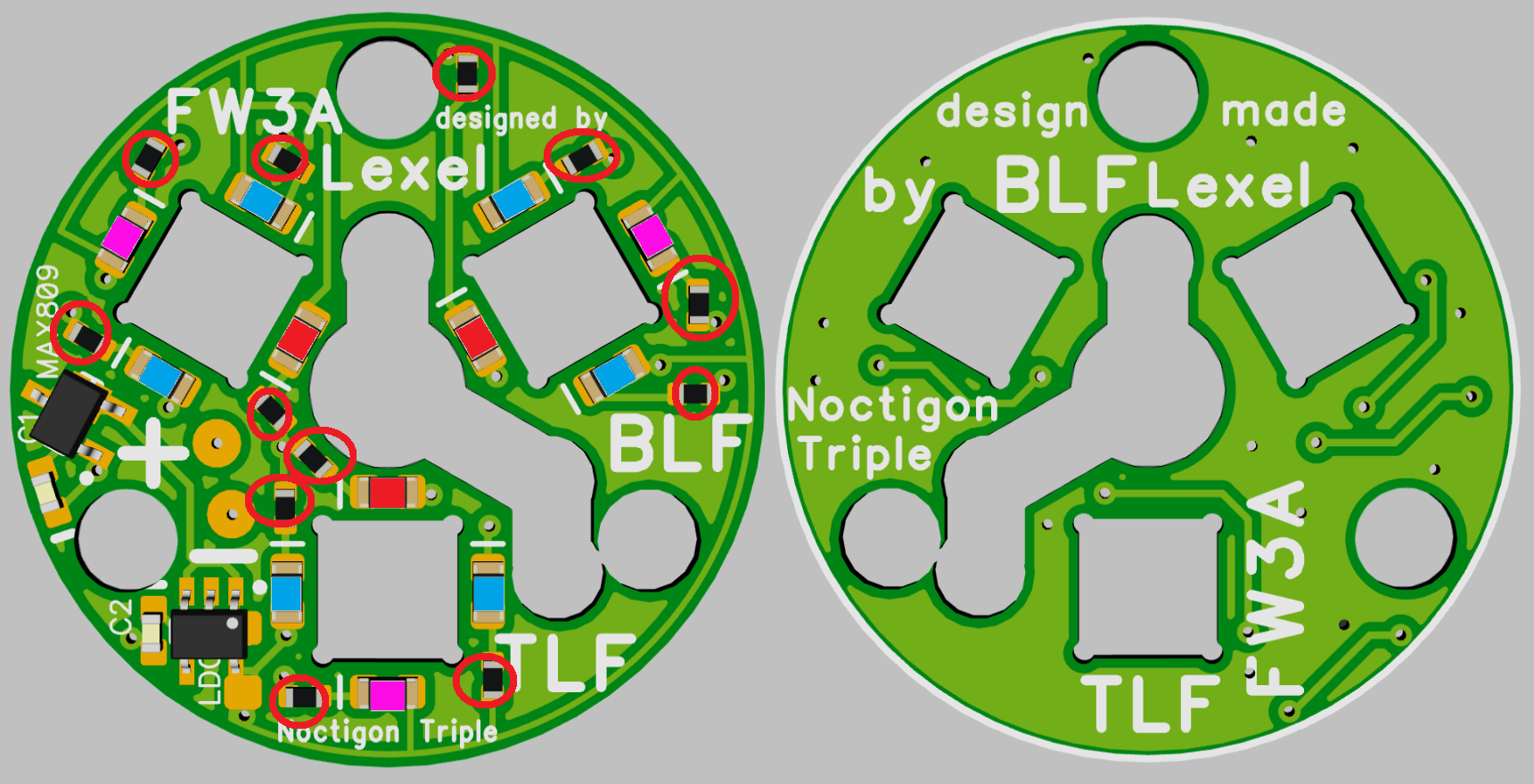
I have shown the full modding guide with flashing that should be easily be done if the right equipment is available
not quite right
if with or without LDO color mixing is always possible
each LED has an individual resistor, the LDO can be replaced with a 0603 resistor, the LVP chip bridged with pads below it
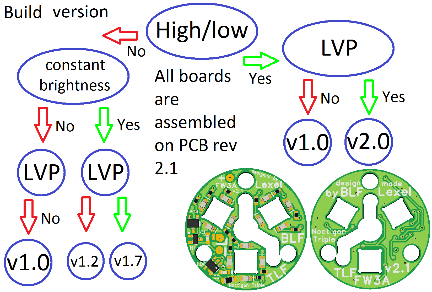
- version with LDO → High/low not possible
- version with LVP → High/low not possible
→ flash #define INDICATOR_LED_SKIP_LOW setting as well
LDO → constant brightness and color mix over full battery voltage
LVP → shuts down when battery low (2.93V without MCU, 3.3V with MCU used)
I plan a version that allows LVP and high/low, but this means a 3. wire for the aux board
this will be then v2.0
If it’s controlled by MCU does it also have OFF? Also, with it wired this way can I also re-flash the firmware while aux board is connected?
If I want 1 or 2 color + MCU (low/high/off) it’s only 1 possible option right?
This is fantastic! I have questions, though. Forgive me if they seem elementary.
1:
If I wanted the same colors in the prototype (yellow, ice blue, and pink??), with matched brightness, and LVP, would I choose 1.7?
2:
Then, I can choose to either have the MCU control them or battery voltage. Since LVP doesn’t support high/low, is the difference:
- MCU: aux board turns off when main LEDs are on?
- battery voltage: aux is always on?
3:
To use battery voltage control, it says to bridge MCPCB+ to the aux+. Do I just connect a very small wire from the MCPCB to the aux board? In that case, it seems nothing gets soldered to the driver and the driver doesn’t really need to be removed. Is that correct?
Edit: I just realized this would result in the aux board ONLY being on when the main emitters were on, so I guess the bridge needs to be from driver+ to aux+? Where on the driver should this bridge wire attach?
4:
If I wanted the aux LED brightness to be the same as a D4S with cyan aux on the low setting, how would I specify that?
Thanks so much!
Mike
MCU has always ON/OFF/Beacon
the simple solution is connected to battery voltage and always ON
Gen1.0 also supports LOW similar to Emisar aux board with one 0603 resistor to adjust brightness,
but in addition each LED has a balance resistor to mix colors
LVP or LDO are not compatible with LOW setting
I am not sure if the input cap of the LDO lets you flash the MCU when there is no LVP or if the LVP chip is there
but to flash the driver you have to disassemble it anyway so the question does not make practical sense
1. Prototype uses warm white not yellow, as its way more efficient
you can use v1.7 for LVP and constant brightness independent of battery voltage,
but also without the LDO the colors get matched pretty good by the balance resistors,
but a slight shift can be seen over the battery voltage,
most important is without LDO the LEDs get dimmer with drained cell voltage
2. Yes Aux board has to be flashed OFF when main LEDs are on, as it doesn’t support the aux ramping (only v1.0 works with low and ramp, but it makes no sense)
On battery aux LEDs are always on, not a big problem with low brightness, if you run them with 1mA or so it will be relative bright compared to moonlight
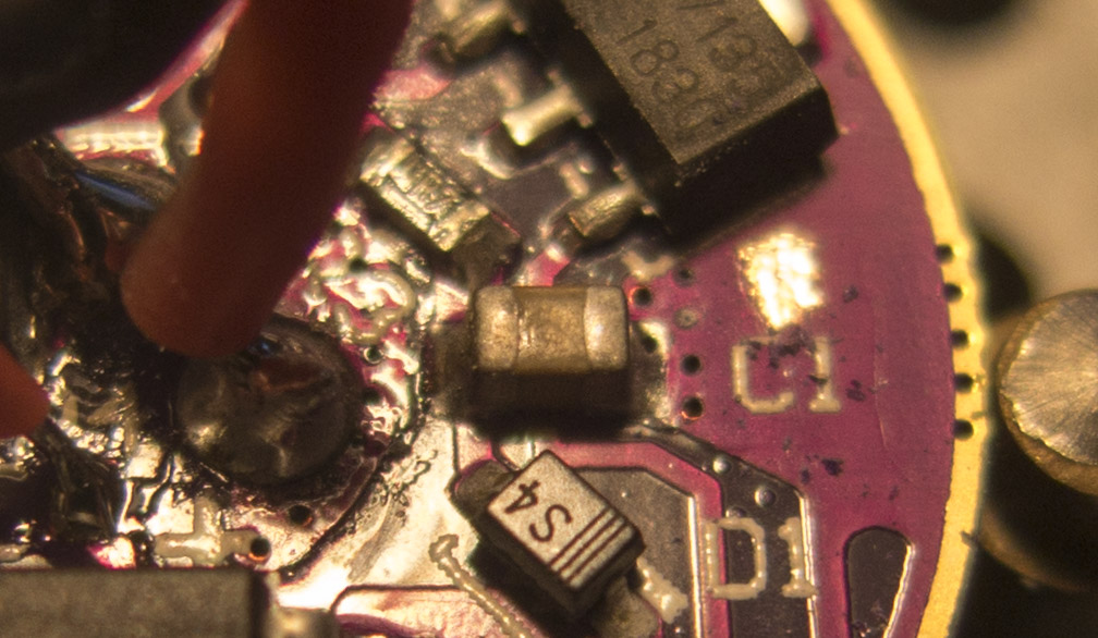
3. you always need to get ground to the board to run it, you can use + from the MCPCB,
but ground needs to be pulled from driver or the flashlight body
You can solder + to red MCPCB wire and ground to the plane I scraped off the paint next to the AMC, or solder directly on the AMC fin
Thanks for the reply, Lexel. I think I want high/low capability, which means Gen 1. I keep my batteries charged so not having LDO and LVP is ok.
With Gen 1, can I get low and high brightness similar to low and high on a cyan D4S?
I am able to flash Anduril, but I’m not set up for compiling. Would someone be able to post both the regular and 219B hex files with the changes already made for the aux board?
D4S uses a fairly high brightness, I would reach about the same with “2mA” setting
Actually, I’d be ok with the high being a little dimmer than the D4S high.
I’d like the low to be about the same as the D4S low, though. I use it on my nightstand facing the bed. Is that possible?
I realize I’ve been occupying your sales thread. We can move to PM if you like.
low is always based mainly on the internal pull up resistor in the MCU, nothing you can change there
selection guide added
I also compiled hex files for the FW3A, but they are untested yet
It’s not stock Anduril there are some changes
http://www.metronixlaser.de/bilder/flashlight/FW3A/Anduril_aux.zip
Payment sent for two v1.7 boards. Thank you Lexel!
Lexel, the link to the zipped hex file you mentioned previously says “File Not Found”.
updated
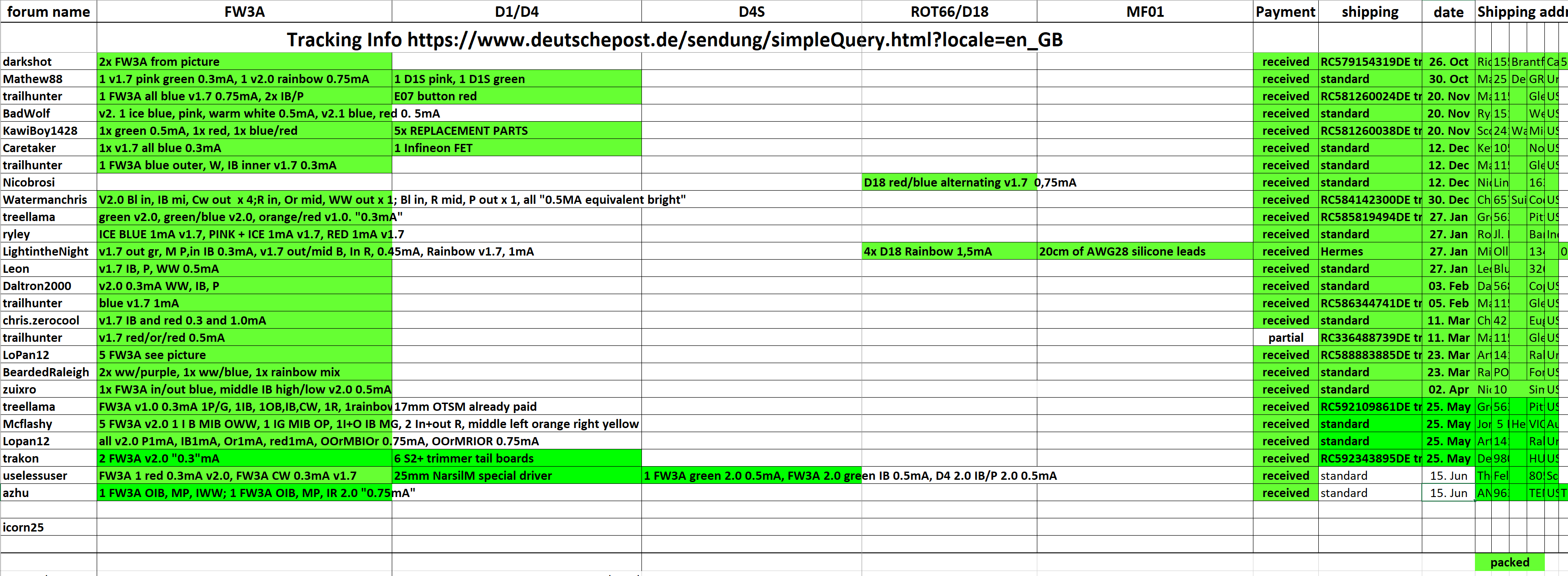
a few shippings today
Thank you Lexel! I’m excited to install them when they arrive.
This looks awesome. It may be enough to convince me to learn to flash my board.
flashing is just the top end mod, you can simply put it on the battery as always ON
If I do it that way will it affect the tint of my light?
the Aux LEDS mainly light outside the beam angle of the regular LEDs and only with very low brightness
you won’t see it at distances above 20cm even on Moonlight
Awesome, thanks. I will be ordering.
Edit; posting my final changes now that Lexel has replied:
cfg-fw3a.h ADD TO END
hwdef-FW3A.h ADD/CHANGE
same as any other Aux HWdef, but you need to disable the optic nerve
//#ifndef VISION_PIN
//#define VISION_PIN PB2 // pin 7, optic nerve
//#define ADC_CHANNEL 0x01 // MUX 01 corresponds with PB2
//#define ADC_DIDR ADC1D // Digital input disable bit corresponding with PB2
#define ADC_PRSCL 0x06 // clk/64
// has a lighted button
#ifndef AUXLED_PIN
#define AUXLED_PIN PB2 // pin 7
#endif