Okay, I've thought about the acknowledging sequence a bit and I think I've found a way to do it without falling back to mem-switching. We could keep the short-short-long-short sequence and abort programming once the light stays on for more than two seconds. This would effectively prevent any accidental re-programming and should be quite easy to implement. Although there will be yet another case of #ifdef...
This is probably the last feature I'll be adding to the driver, as it has already reached a state where it's really hard to read the code and see what's going on.
A WF502B-R5 was modded with version 3 of Tido's BLF-VLD program. I choosed to make a simple 4 mode light with low battery detector. The modes was layed out as 1.5%-6%-25%-100%, the result in (my own)lumens was 3.5-16-66-240.
The program now has battery low detection. When the battery voltage drops under about 3V the light will revert to lowest level and will blink every 5 sec's. This is a matter of taste, perhaps it should only blink as a warning, but then it could not be left alone without damaging a battery without protection. Perhaps the best would be that the light stepped down a step at a time (how about that, Tido?). This is easily done manually by just restarting in a lower mode, the detector will not cut during the first few sec's.<(Edited): The Low Bat function is now changed so that the output repeatedly will be cut to half every time the battery voltage fall to 3V. That way the output will be optimized to the remaining charge until the LED only glows. This works very nice.>
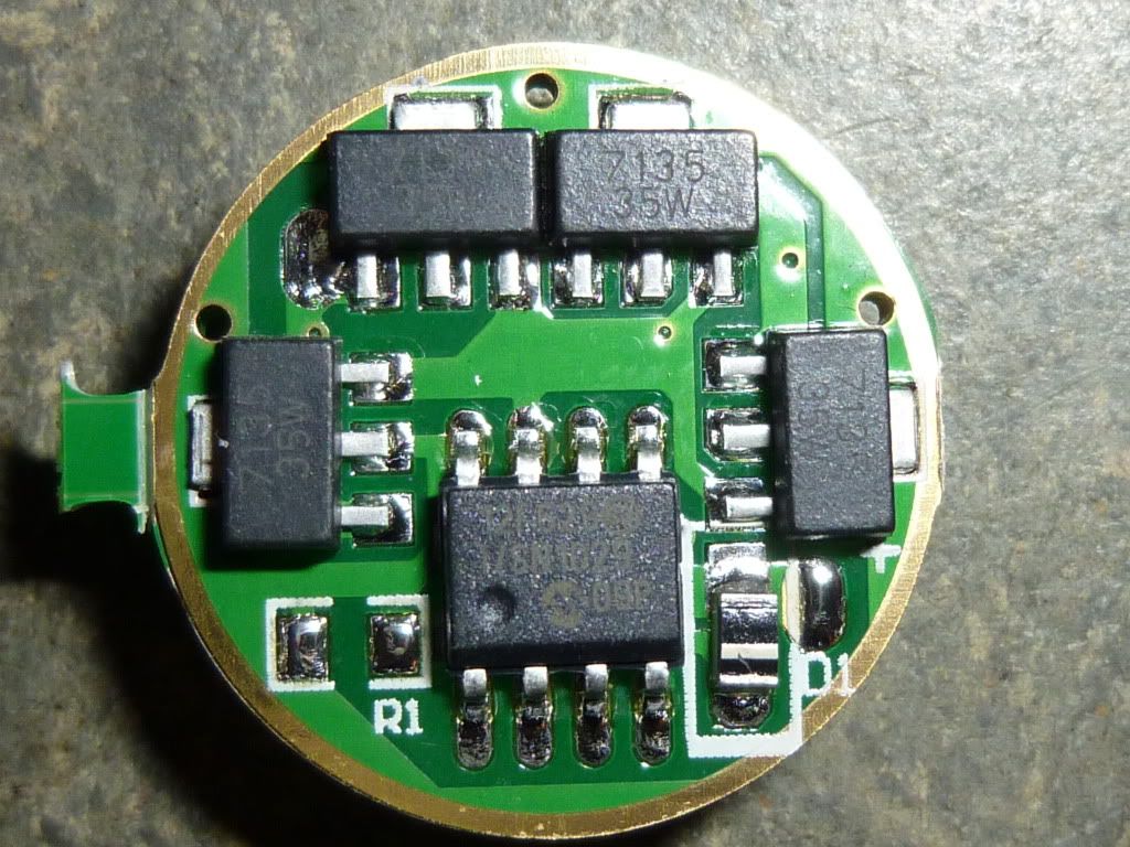
At the top a fourth 7135 is added to obtain 1.4 Amp. At the bottom, the wire connecting the chip to the memory circuit on the other side is visible. At the right a new, round diode - I used the original, smaller doide in the circuit underneath as the round one was too long. <(Edited): I have changed the diode back again! the original diode is a Shottky type to keep the chip running at low voltage.>
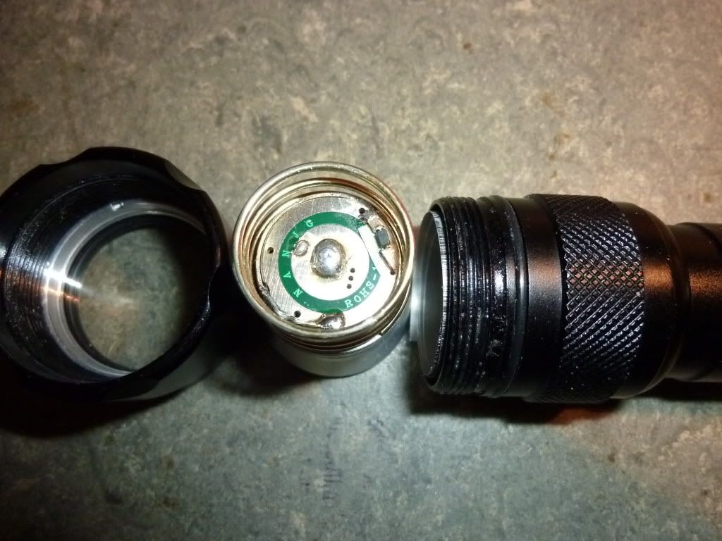
The 3 added components to make the memory_after_off (as in TR-801, EF23, Skyray S-A1, F20, C3 SS, Z1, WF501B-MC-E, ...). A diode is soldered 'piggy-back' on top of a resistor of 10MOhm (invisible in the picture), both soldered to a capacitor of 100nF to the outer ring. The isolator underneath is a piece of tape for painting. These components are not nesessary if you prefer a memory_after_on type (as in Tank-566, TrFi.R5-A3, WF502B-R5, ...). The PIN_SWITCH variable in the program should be changed accordingly.
The pill in place. In the tube two full rounds of Pepsi-Max alu-can is fitted for better cooling.
EDIT:
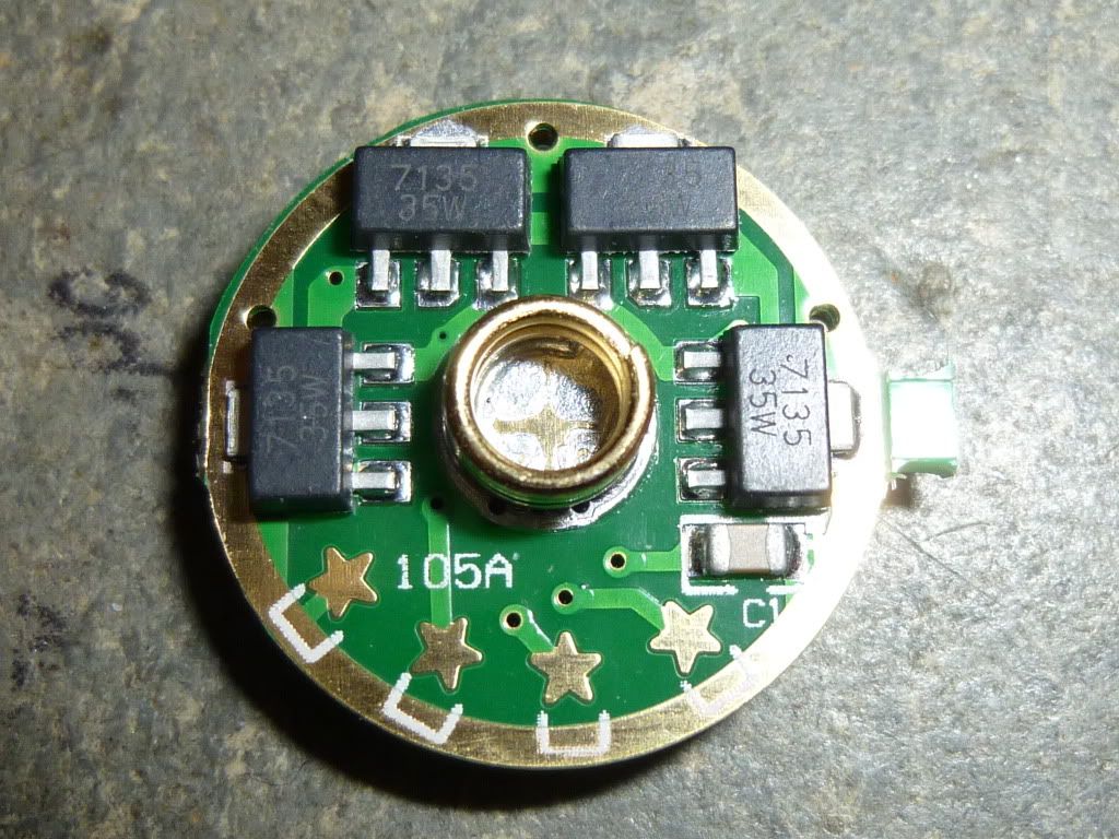
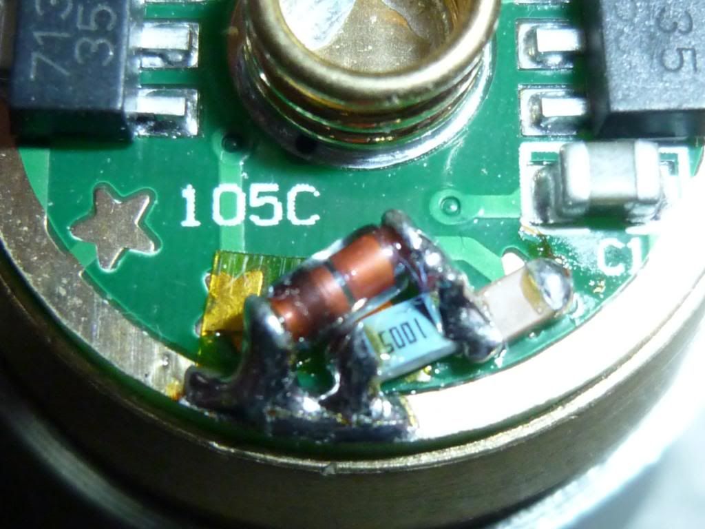
After a few broken capacitors, I changed the mounting method to a more rigid one. Here shown on a NANJG 105C which already (like the AK47) has a star that is connected to the MCU pin 2 so a wire is not needed. This makes the mounting of components and also a later reprogramming of the MCU easier.
I put a piece of Kapton tape besides the rightmost star to isolate the other stars and solder the capacitor to the rightmost star. Then from the free end of the capacitor I solder the resistor and the diode (cathode) to the outer ring (see picture). This circuit has exactly the same function as the former but is more mechanical stable.
That is fantastic! Absolutely amazing and incredibly tiny detailed work. I guess the PWM has been set fast enough where it isn't noticeable or are there problems setting it so high for so little output?
The PWM frequency is 1.1 kHz. The light is rock-steady on lowest. The actual PWM output design values are 0x04 - 0x0F - 0x3A - 0xFF. There are no problems in lowering the low value down to 0x01 but the output is not quite linear at the lowest values. To make 1 lumen I would guess the output should be 0x02.
About the mem_after_off, it is sensible to bad connections and could shift level by knocking on the light. Perhaps 10uF across the chip could help. But it sure is my preferred kind of memory.
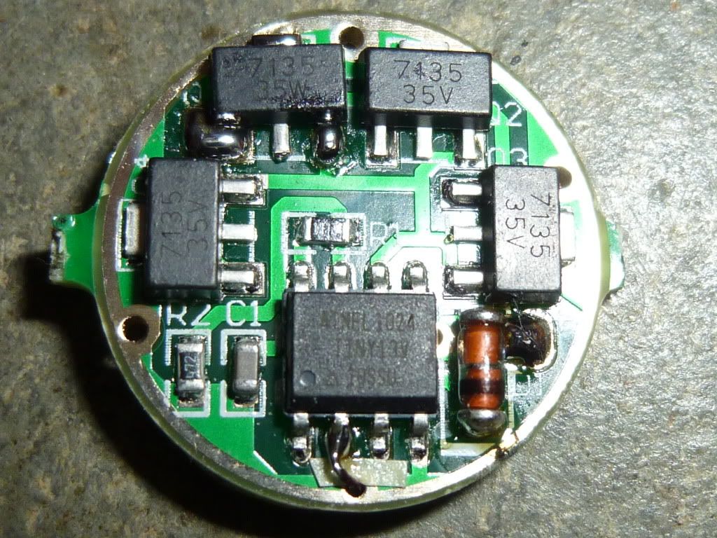
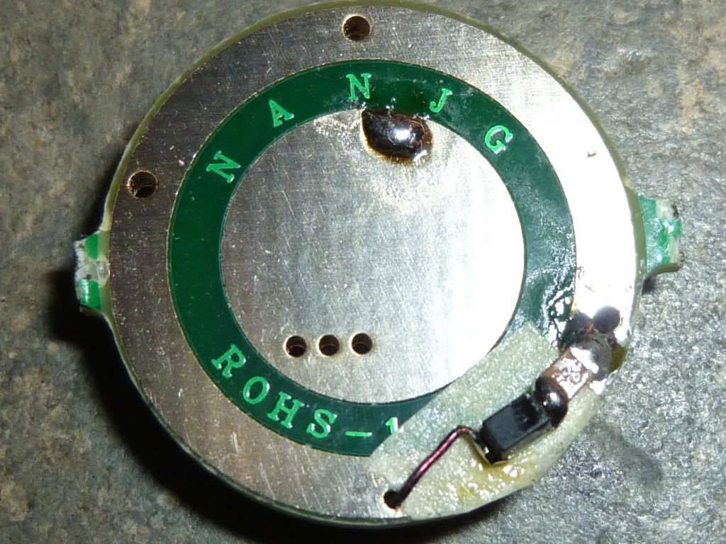
Again I have to issue a warning. This time it is the NANJG 105 driver from KD . They have changed it to 105A and it has a PIC processor (luckily I have two of the old 105 with ATtiny for my upcoming XM-L's). Here are pics of the two sides:
At least it has stars so it is possible to make a 3-mode (I hope). I expect it has memory after ON plus 2 sec.
Now to the big question: are drivers with ATtiny about to die out?
That would be a real bummer, the Atmels are the easiest to re-program. OTOH, I've got a PIC-Kit2 programmer on the way, so this is a strong incentive to port the BLF-VLD to the PIC platform ;)
Hi, I followed this thread with great interest, and I already programmed some kind of flashlight driver (a somewhat special thing for geocaching though, not a general flashlight; wanted to do that next).
I too got the new 105A from KD (unfortunately a 5-pack), while I earlier got two 105 ones. And fortunately I have still some AK101 and AK47 around.
I just got into programming AVRs (WinAVR/AVR Studio), I don't know if I really want to adapt to PICs, too.
I wonder about code efficiency... The 12F629 has space for 1024 instructions (of 14bit each...), which is more than the ATtiny13 (1024 Bytes for 512 two-byte-instructions), but tiny13 has a bigger (more powerful?) instruction set (120) than the PIC (35). The available free compiler (Hi-tech PICC lite) probably will optimize less than the avr-gcc - So I'm looking forward to your porting reports.
Furthermore the 12F629 doesn't have ADC nor PWM (as far as I know). -- I prefer AVR I guess :)
Did you order a 'real' PICkit2 (~33 EUR, ebay) or a cheaper clone (~17 EUR, ebay)?
I have been reading this forum since almost two months ago and I like the fact it is for BUDGET lights. I like budget flashlights because I like to play with them replacing leds and drivers, something I won't do with expensive flashlights. The expensive flashlights I have are collecting dust just because I almost don't use them.
Considering some people here is wanting to use PIC microcontrollers I am posting this information I posted some time ago in another flashlight forum.
I have written and tested this PICAXE source code to implement multi-level functionality in DX SKU 15880 or any driver using Microchip PIC12F629 microcontroller.
The test was done using a regular LED instead in the actual driver. It must work in the actual driver.
You need to replace the stock microcontroller with a PICAXE-08M Surface MountAXE007MSM device. You will also need to do some pin swapping and lifting since PICAXE-08M uses pin 5 to do PWM and DX SKU 15880 uses pin 7.
I used PICAXE mainly because there is no necesity for a programmer to burn the program into the device. A computer with a serial port (or USB to RS232 converter) and 2 resistors is all needed to program the device.
'LED PWM Driver software.
'Writen by Juan C Galvez
' the following EEPROM entry contains the desired level percentages
' The first entry contains the level position to use the next time the driver is powered.
' Next are the desired level percentages.
' The last position next to the last desired level must be zero. It is used as end indicator
' Example EEPROM entries:
' 1, 1, 50, 100, 0 means 1%, 50%, 100%
' 1, 10, 100, 0 means 10%, 100%
' 1, 10, 30, 50, 100, 0 means 10%, 30%, 50%, 100%
' No SOS nor STROBE implemented.
EEPROM 0,(1, 5, 50, 100, 0 )
symbol LEVEL_SHIFT_PERIOD = 3000
' b0 keeps the current level positi b0 = b0 & $0F
' bit7 If 0 then keep the current level. If 1 then go to next level. Note: bit7 if the MSB in field b0
' b1 Current level value (%)
read 0,b0 ' Read next level position
if bit7 = 0 then ' If bit 7 not set the keep the current level.
read b0, b1 ' Read current level value
else
b0 = b0 & $0F ' Turn bit 7 off before reading position value
do
b0 = b0 + 1 ' Go to next level
read b0, b1 ' Read next level value
if b1 = 0 then ' If next level value is zero then start over.
b0 = 0 ' Reset position
end if
loop while b1 = 0 ' Keep until a valid position has been
end if
bit7 = 1 ' Turn bit 7 on. This means that the next time the driver must go to the next level
write 0, b0 ' Write the value to EEPROM position 0
w1 = b1 * 4 ' Multiply level value times 4
pwmout 2 , 99, w1 ' Turn the LED using the current/calculated level
pause LEVEL_SHIFT_PERIOD ' Wait n seconds
bit7 = 0 ' Turn bit7 off so the next time the driver is powered it will keep the current level
write 0, b0 ' Write current level position to EEPROM
b0 = 1 ' Enter an infinite loop
do
pause 2000 'Used to allow firmware upgrade while running.
loop while b0 = 1
As written, the code implements 3 brightness levels 5%, 50% and 100% but that can be easely changed. Also, the level change occurs if the driver is powered for 3 seconds; I mean, if you turn the driver on and keep is for at least 3 seconds then the next time you turn the driver again it will start in the last used time. I you turn the driver on and turn it off before 3 seconds then the driver will use the next level the next time it is turned on. To change this 3 seconds just modify the line containing:
PICAXE is interesting and somewhat strange... From the specs it seems that the flash memory only contains the PICAXE interpreter while the user program is loaded and stored in the EEPROM (probably tokenized) and interpreted by the (flashed) interpreter. I have seen something like that in an ATtiny2313-based educational set.
My plan for building that driver is to actually keep the µC running for a while after the user has switched the light off. I'm going to use a bigger capacitor parallel to the µC, so when the battery power is off, it runs from that. Some battery sense pin is required to check if the flashlight is on or off, and sleep with watchdog is engaged as soon as power goes down (via interrupt). This allows timing the 'off' taps for mode changes etc. Since programm logic will be simpler, it might even use up less memory and leave more space for fun ("Hey look, that light says my name in Morse code!" :) )
When I first thought about the the BLF-VLD, I wanted to keep the MCU running too, but I soon realised that this just wouldn't work with the standard PCBs available. For one, almost all ATtiny based PCBs have voltage dividers for battery monitoring, that will suck a buffer cap empty in a matter of milliseconds. Second, to actually detect the power-off, one would have to add a wire directly from the battery's positive end to an I/O pin, circumventing the protective diode. As a major design goal was to have a driver program that could be flashed into a stock PCB, that was the end of that idea ;)
AFAIK, most PIC based PCBs don't have the voltage divider problem, as the 12F629 doesn't have an ADC and therefore can't monitor the battery's voltage. But you'd still need to add the wire for detecting power loss and would probably have to upgrade the buffer cap.
 (luckily I have two of the