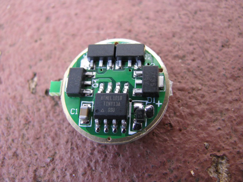
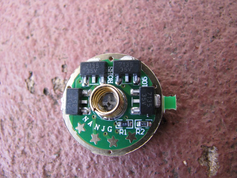
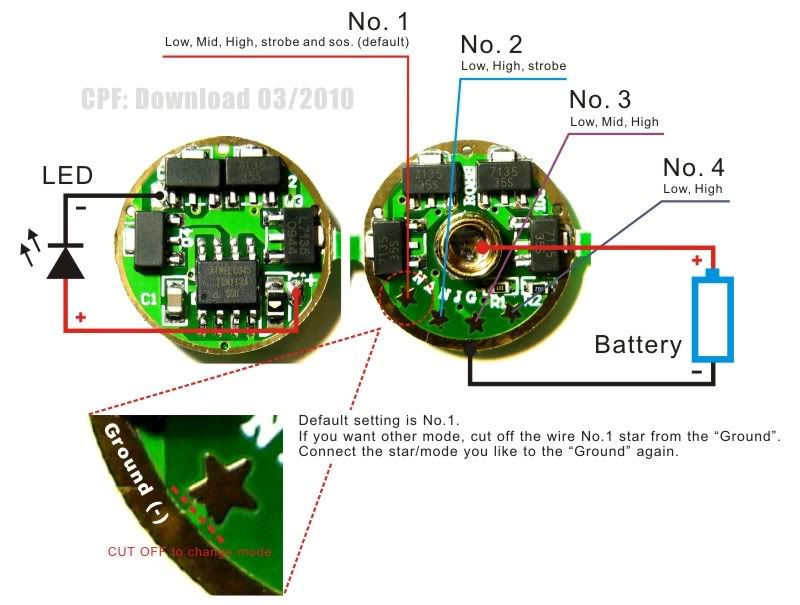
I got my NANJG 106 (could be 105; it's hard to read) on Friday with my XM-L drop-in. I had been having trouble with my MC-E drop-in so I thought I would put it in there. I ran into a few problems getting it soldered correctly and then found a short in my LED + lead, but finally got the light working. I put in a little piece of wire from the 2nd star (clockwise) to the outer ground ring to get 3 modes instead of the default 5. It works, I got a draw of 2.2A on a battery at 4.1V, so I am charging it up to see if I can get more than that (got more like 2.5A on a 4.2V battery which may be about all my DMM will read or all the battery will supply).
Anyway, Low and Medium on this one have absolutely the worst PWM I have ever seen. Hopefully I didn't mess up the LED, but it seems like it would either work fine or it wouldn't instead of somehow impacting the PWM rate. Also there doesn't seem to be any mode memory; at least on the 3 modes I have it set to now it always starts on Low, which is not how the SB version worked. Anyone else have any experience with this? If I can get my AVR equipment to work, this driver could be a good candidate for reprogramming.
Kai Domain: http://www.kaidomain.com/ProductDetails.aspx?ProductId=10995
Here is the current one that Shiningbeam is selling, but it looks different from the one I bought, which looks just like the KD one. Maybe the KD model really is 105 and this one is the 106.
Forget to say, mine was from KD , could read 105, the memory work fine just as an AK-47, it seem the same with more 7135
"I think you want to use the 10A setting because it has less resistance and will give you more accurate and consistent readings."
I know that just did not realize how sensible at resistance are those circuits, actually an ampere meter is a volt meter which test the drop voltage trough a shunt resistor , in 2A setting is five more resistance than in 10A.
Also the regular test probes don't work, to a proper measure is need short tough wires.
My mistake was due the fact that more digits mean more resolution, in a 10A setting 438 mA is show as .43 A.
how are the modules pulled to achieve 1.4a? can you just take whatever ones off you want? or is there specific ones? i'm guess you just desolder them?
also I have a copper slug I want to solder to the + battery connection..should I just put solder on the end of the copper then heat the other end?
still waiting on this driver to come in so appreciate any help in the install process..soldering to the led is not an issue nor is the other driver to pill soldering..just wondering about the contact spring area..
hmm were very easy with my solering iron..it's a 25w fine tip pencil style..what are u using? use thin style flux core solder and pre-tin the wire you are soldering..that and holding the wire with a tweezer or needle tip pliers might give you better control..
Might help to put a little bend in the end of the wire. I can hardly even see what I'm doing because everything is so small. I just keep trying until it sticks. As long as there is enough solder on the pad, you don't hardly need any additional. Maybe just a tiny bit on the iron.
I usually put some solder on the pad, some older on the wire, and just hold the wire to the already tinned pad and with a touch of iron it binds there. There is no way I could use solder, wire and iron at the same time, apart from through hole components and PCBs.