subscribed!
Thanks for the update ltp. I wondered what I was going to use it for. Can you make me a holder?
I got around to fitting the index wheel. I had a use for it so ‘had to get it done’.


I really needed to make a spindle lock as well but couldn’t come up with a suitable idea and I was impatient to get the job done so used this ingenious contraption.

The compound slide also needed some attention. The small bolts that lock down the compound angle were starting to strip the threads so I fitted some larger bolts. It took a bit of shaping of the bolt to get it into the t-slot. The pic below shows one old and one new bolt.

Here’s a pic of the project.

Nice finish up pp. Where do I put my order in for the degree wheel mod? ![]()
![]()
I’m jealous pinkpanda3310, your comp cam wheel has the full 360 degree increments. :cry:
Looks good and should be pretty useful. :+1:
Finally able to reply. Went to the eye doctor and have had blurry vision all afternoon :confounded:
Like you need one with your mad skillz ![]()
I have you to thank for the idea so… err… Thanks! :+1:
nice pp ,curious as to what the project is
It as for this crazy Titanium light pp built.
so I have been quiet for a bit,
but decided to cnc the mill drill,still using the original screws
and very basic bracketry (work in progress)
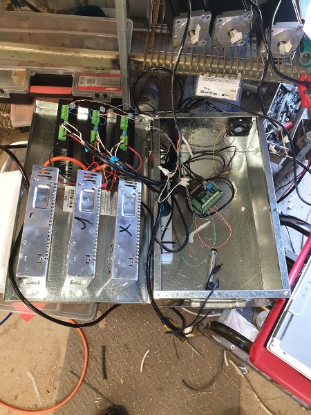
power supply’s stepper drives ect
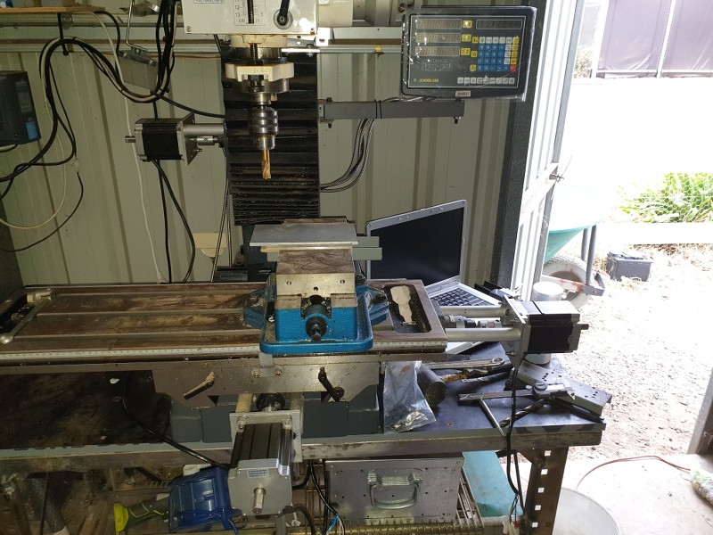
the old dell laptop from 2004 got a new lease of life with Linux cnc installed

updated the drive for the head with a belt reduction and fitted a gas strut to the other side
has improved “z” speed a bit (12”per minute)x and y are about 40”minute
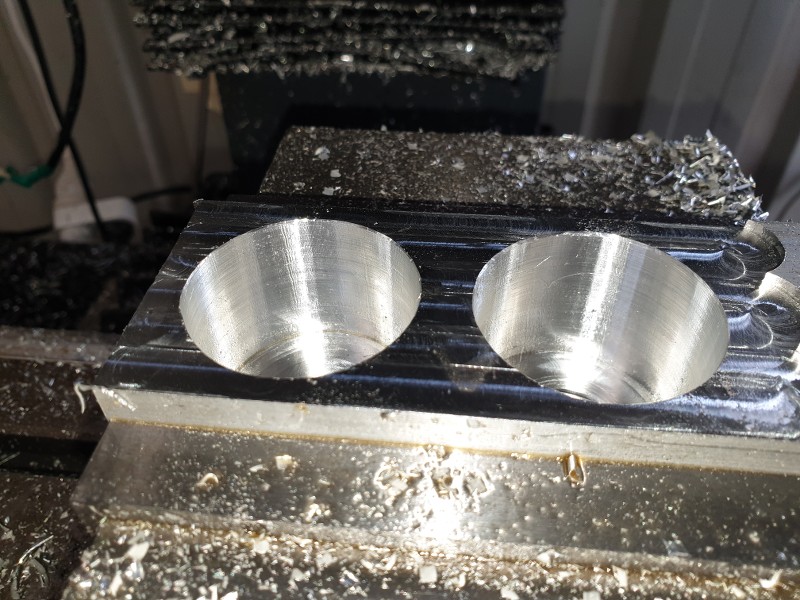
bored a couple of holes and did some facing using a10mm end mill.holes are .004”
elongated but accurate enough for most chores. Ball screws would improve it but would increase the cost

one thing it does do is make a mess (14 mm endmill boring plate for column mount)
been making a few signs for family ad friends more to learn the cad/cam/G-code. side of things,
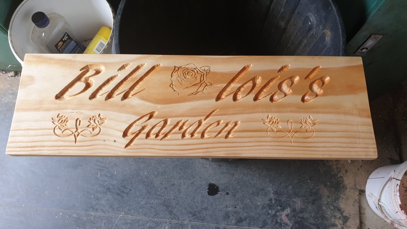
It’s a bit of fun.
It doesn’t “look like you’ve been quiet”
Awesome project :+1: :+1:
I had the privileged of seeing lostheplots nc mill in action last weekend. He is one very smart cookie. To say the problems he had to work out would have put many others off but he stuck at it and made a terrific machine. Now what do we all want made. ![]()
Ah, had a great ride with him, lostheplot and my nephew as well. ![]()
What I do is to use a large square, (ground on all sides) tool bit and hold it tight between the work and the chuck face for a quick fit up. If you have a large enough space behind the work to slide it between the jaws. You may be surprised how true it runs for general work. Just be sure to pull it out before spinning up the chuck 
primitive copy turning attachment for lathe

same idea could be used for any shape.
I made one of these out of a bicycle seat cam lock several years ago and it is a very useful tool on a lathe.
You attach it to the bed rail and move the carriage to where you would like to stop turning on a work piece. Then push the carriage stop up against the carriage and turn the handle locking it in place. So every time you move the carriage towards the chuck turning down the work piece it hits the carriage stop and the carriage stops precisely in the same place every pass.
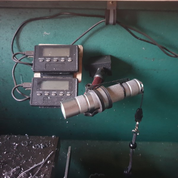
I have plenty of light above my lathe but for inside tubes etc… it’s not so good. So I slid a magnet under the clip of an at40 so it can easily be mounted just about anywhere on the lathe


Is that a new tool holder?
Nah, had it for ages
pp I do something similar
a mag base and a p clamp and whatever torch is close handy.
My tool post spindle is great but it has limitations. The ER collet is so small i can only fit drill/dremel bits up to 3mm. So I’ve made up a new tool post spindle that should be able to handle much bigger stuff. It mounts in the same clamp block as the old one. I had some grief when i pressed the bearings in, it was a little too tight for the tools i had and used the big vice at work to get the job done. Unfortunately it’s squeezing the bearings enough to make the spindle feel a little stiff. Hopefully it’ll wear in…


I tested the spindle speed with a tacho i don’t really use anymore. I was hoping for a little higher revs but to be fair the squished bearings are producing a fair amount of drag/load. I just need to make a neat spot for the electronics then it’s ready for a test run.

