Ok, I tried to take it apart while waiting on vendors response for repair parts. Online video shows while the disassembly while its doable, but its getting into the “a bit more work than I care to do” territory. because of the retaining hw, it requires hunting down a tool I don’t have, and because of head button, the assembly is a hair more tricky.
while looking at the board, I tested the following with a voltmeter.
1+2 has good voltage
3+4 also has good voltage 3.65
Does this mean the led is the only thing i need to change out? so I just need to source a sst-40 dedomed (upgrade I was thinking :laughing: and solder it on?
I just dropped my FT03 from about 3 feet and put a crack straight across the lens. No luck finding a replacement lens. Does anyone know where I can get one for a reasonable price?
You can’t really test a driver this way. It changes current, not voltage. The number 1 in your pic, red wire, is straight battery power. If you put your negative probe to the aluminum body you will always get battery voltage.
Do you have any old LEDs already mounted to a star or an old junk flashlight you can take the led out of?
You need a cheap pair of snap ring pliers to loosen and tighten the driver retaining ring. I use a cheap $5 set like this.
Measure the diameter and thickness and search the internet. I replaced the lens in my Q8 from a shop on Aliexpress and total cost was $3. It was not fancy AR coated, but that is no big deal to me.
Okay will do thanks.
Edit: Bought from this seller on Ali - the size is 0.9mm smaller in dia but I don’t think that will be critical, in fact it might save it from cracking if I drop it again.
Ok, I got the tool and opened it, now I can see the led is well sealed on a copper heatsink, the while film probably helps reflect light and hide the board, and I am not sure how I would remove the led when it’s time to replace. Funny enough luminous hq is local to me, if I can only get them to sell me a sst-40:)
I bought a cheap flashlight from dollar store to plan on using that led. For diagnostic can I just run 2 wires from the sst-40 to a good led? If it works with some ramping on 3.3v (3 old aaa) what’s next? It seems the sst-40 is difficult to remove/install.
There is no white film. that is just the centering ring, it lifts right out.
The board is held in by two screws.
Just desolder the two wires and remove the screws and the board comes right out.
Can I test this without desoldering? Considering that this is on a heat sink, it’s gonna be tough to desolder. After desolder the screws are shown? Meaning the solder is on the screw right now? Looks like led is either on the copper by itself or the white part is a very thin board that’s some how stuck to the copper.
You are making this way too complicated. And I am a newbie!
Put the screws back in. All it takes is a touch of a good soldering iron to remove each wire. Just hold it with a tweezer or needle nose, touch the soldering iron and pull it off. THEN take out the screws and remove the copper board.
You can put in a new board or reflow the LED. Search for that.
There are normally two screws holding the board down. They do not appear in the photos
Why in the world would you cut the wires when you know you have to solder them to connect them back?
That’s what I am saying, if I am replacing that copper assembly then I can just cut it and use twist and shrink wrap / tape. I guess I need to find out what I am replacing either just the led or that assembly. If it’s just led I don’t see how that can be done…I don’t know how they’ve attached the led to the copper
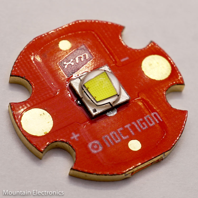
He will mount the led on a board for you. The board is a mcpcb or metal core printed circuit board and is sometimes referred to as a star. You will need either the 26mm or the 31.5mm I can’t remember which.
This is the complete unit.
You have to be able to solder to do this repair and your iron has to be strong enough to undo and reattach those 2 wires.