fluke
November 1, 2019, 9:34pm
34
Also did S2+ M3 M21A M21B.
I’ll risk it, much improvement in output?
oweban
November 1, 2019, 9:47pm
35
300-400lm I think - I’m basing it off this:
LED-Test
EN
Luminus SST-40-W Specialty White LED
SST-40-CW-A120
UPDATE --- 06/23/18 --- raw data added! (link )
This is the english version of my first test (August 2017). Because of more accurate results and some minor changes in the text the german version is no longer valid anymore!
I bought this emitter at Kaidomain several months ago.
Technical data
Tj 85 °C, If 700 mA
Order code: SST-40-CW-A120 (unless otherwise specified)
Type: single…
My lumen tube isn’t quite ready
Yokiamy
November 1, 2019, 9:52pm
36
I gained around 300 lumen with an R050 on the SST40.
The FT03 is still brighter, its driven quite hard
Barkuti
November 2, 2019, 4:48am
37
KnHawke:
In what reviews I spotted of the SST40 based S21A, when you engage Turbo Mode, it almost immediately starts stepping down, pretty much negating anything useful of that mode.
Wow, so bad?
I have to replace the driver in my nephew's S2+, torch predominantly used with the short tube, guess I won't mess with thermal throttling in that one. The other driver, though, is another story.
kinhcan55
December 2, 2019, 10:13pm
38
Hello guys
Yokiamy
December 2, 2019, 10:35pm
39
Maybe this thread helps, driver might be sonewhat different though
Not necessary, posting detailed (macro) photos will do.
Removing the blueish foamy thing, might help though.
Here we go - not the best macro shots in the world, but a quick one while I have a few moment being left alone https://imgur.com/a/0cqCG4U
my guess would be this one
can you try to measure resistance?
also, try to measure wi…
kinhcan55
December 2, 2019, 10:56pm
40
The M3 has different driver, I’m not sure I find it correctly =((
EasyB
December 2, 2019, 11:52pm
42
Good info. I just ordered a few of these and I’m sure I will do this mod.
These drivers with the stepped modes look like constant current linear mode FET drivers like led4power’s. Is the other ‘ramping’ driver from convoy mentioned above also this type of driver? The description and UI seem strange. Is the current limited to 8A?
jacc
April 17, 2020, 2:25pm
43
Barkuti:
If you do that the driver won’t be able to regulate at all. This means no ramping and no modes. I haven’t tried it, though.
You still need to tweak the sense resistor stack value for it to work. You could try an R004 on top, it could work well or it may not. Add some heatsinking to the thing in such a case, as you’ll be above the maximum power rating for single 1206 resistors (a couple stacked one doesn’t changes this significantly). A good mound of thermal glue above sense resistor and MOSFET could help.
If the driver uses R010 for 6A this means sense voltage is Vsense = R × I = 10mΩ × 6A = 60mV. If you want to add 1.5A, you need Rextra = V / I = 60mV / 1.5A = 40mΩ or an R040 in parallel with the existing R010.
I have not measured how that driver behaves actually but if you really want to be sure to hit 7.5A, add some more conductance is my advice. I’d look for an R030, which would raise the maximum current to 8A theorerical (6A + 2A), albeit it would leave the actual figure in close proximity to 7.5A effective due to MOSFET heating, imho .
Hi Barkuti & folks,
Can I ask, where is the sense resistor on this board to be sure?
I have ordered the 20mm board 6A version which I supposed is the same as the 17mm/22mm one. Would you be so kind to show me where it is? thanks
Look at your link picture and it clearly shows R010
Barkuti
April 17, 2020, 2:41pm
45
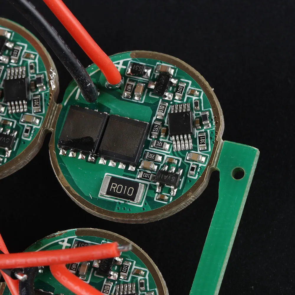
The sense resistor is that big R010 chip resistor onboard, down there in this photo:
That looks to be 2010 imperial size.
jacc
April 18, 2020, 4:12am
46
Thanks for the reply, Guess what? I have bought the 1210 sizes and its on its way! Haha, I read it off other threads of the similar driver but in a 17mm size I think?
Since 2010 size is 5mm x 2.5mm and 1210 is 3.5mm x 2.5mm, I suppose this allows me to join two resistors serially to lower the output (which was my main objective anyway).
I actually do see another R010 on the board, at the left side of the 10pin IC. Could that be the sense resistor as well? Regs
Barkuti:
The sense resistor is that big R010 chip resistor onboard, down there in this photo:
That looks to be 2010 imperial size.
oweban
April 18, 2020, 4:16am
47
The sense resistor is the small black one at the very right of the board in that pic; “north east” of the MCU
jacc
April 18, 2020, 5:46am
48
Oh thanks for the double confirmation. Looks like I will be having a tough time trying to fit 1210 resistors there
I don’t think you’re correct. Barkuti has modified these boards before so I’d be more inclined to trust his answer
oweban
April 18, 2020, 5:51am
50
Oops sorry I was thinking about the thermal resistor. Brain dead lately.
Apologies everyone, barkuti is right. I’ve done the mod on those sense resistors myself.
Anyone know which component is the thermal resistor on the 17mm driver of post #6 ? (bottom picture). There’s two components within the drawn cicle
Barkuti
April 18, 2020, 6:39am
52
The upper one Funtastic . I could also say the rightmost one, and so it is valid for both top (∅22 mm) and bottom (∅17 mm) driver pictures.