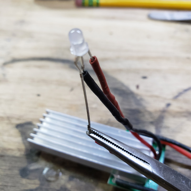
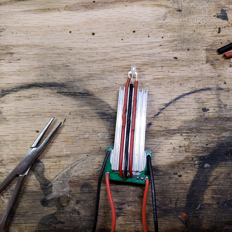
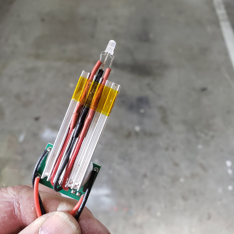
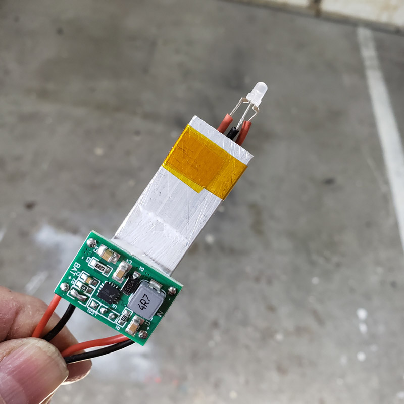
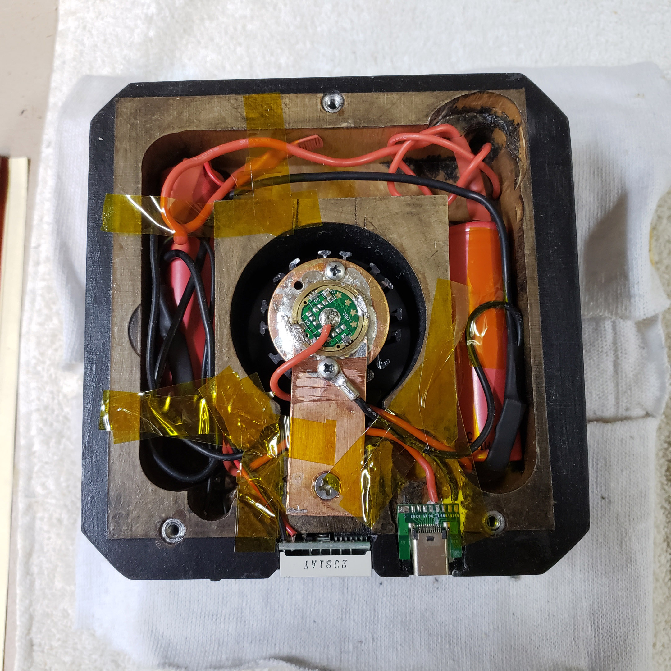
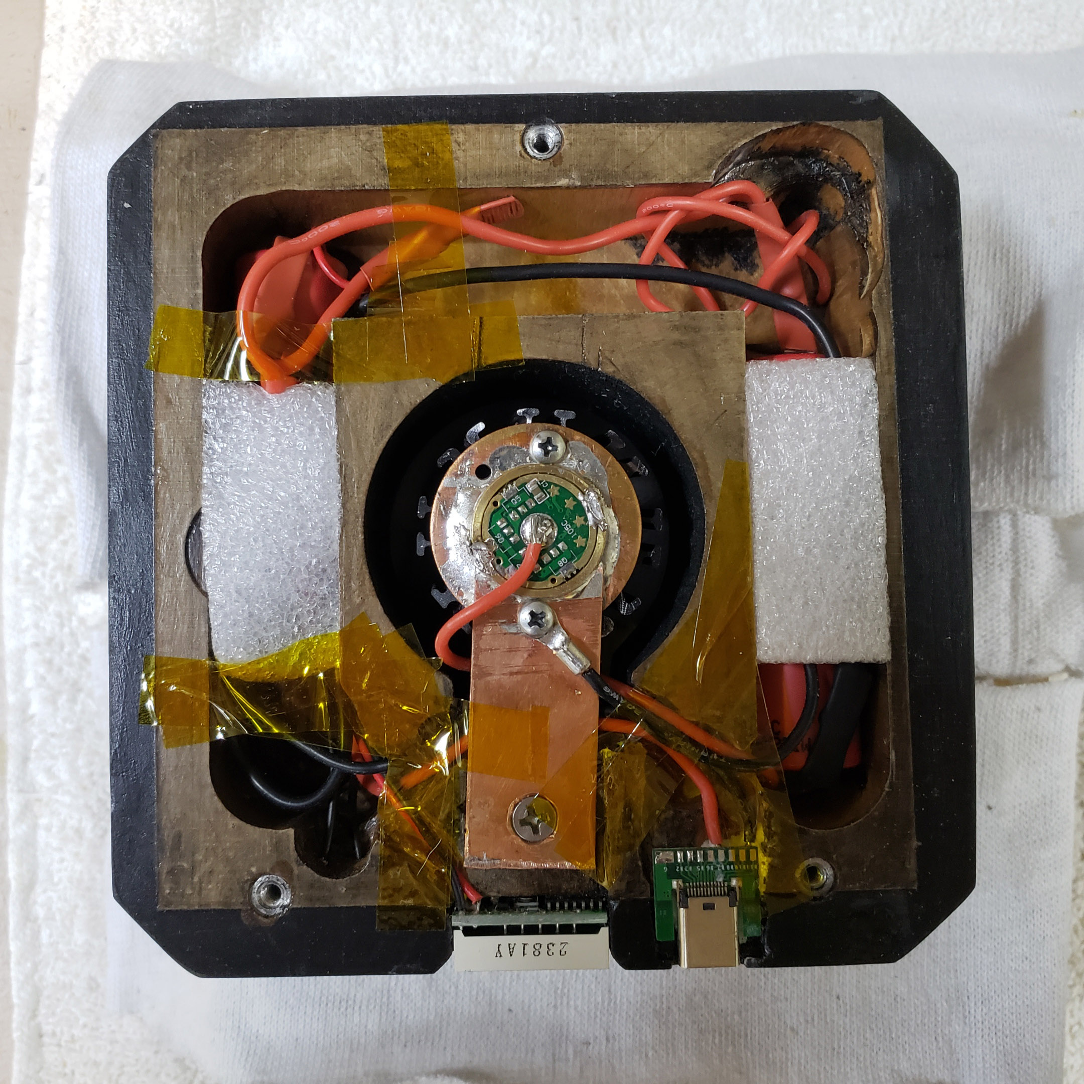
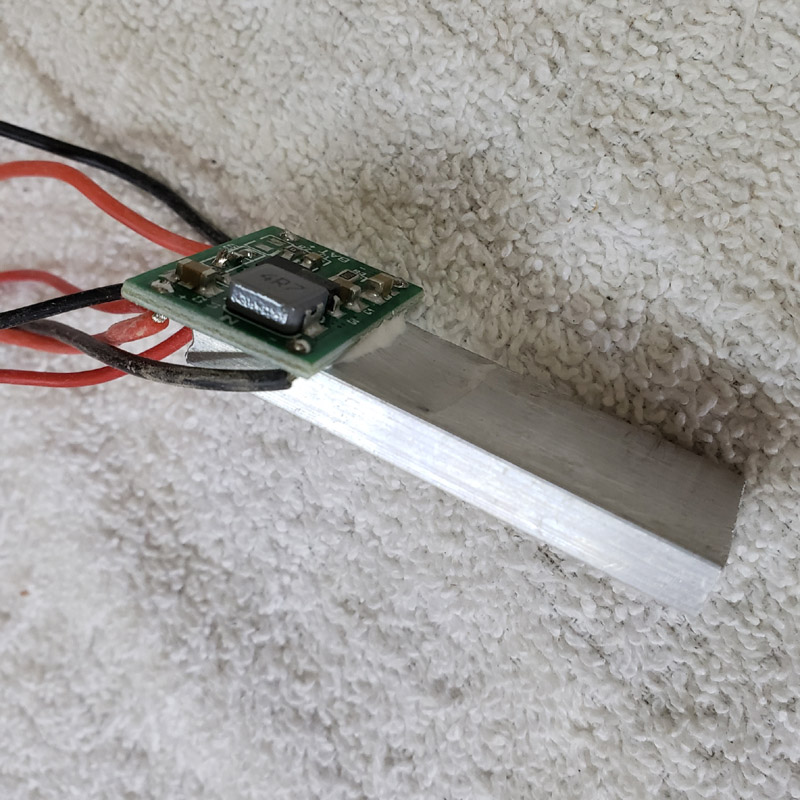
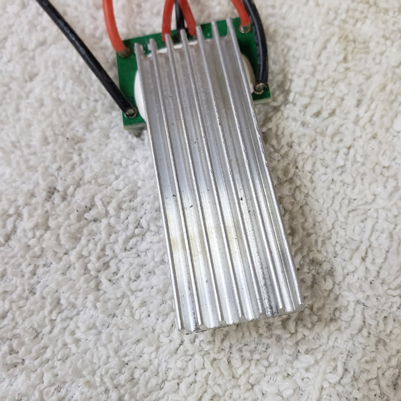
This will have an onboard USB charger. A TP5000 2 amp board. It needs a heat sink. So I cut off a length from a longer stick and used arctic alumina thermal epoxy adhesive to mate the boad and the sink. That is a lot of wires, yes; 2 for power input, 2 to the cells (2 x 18650 in parallel) and three to extend to the red/green led indicator.
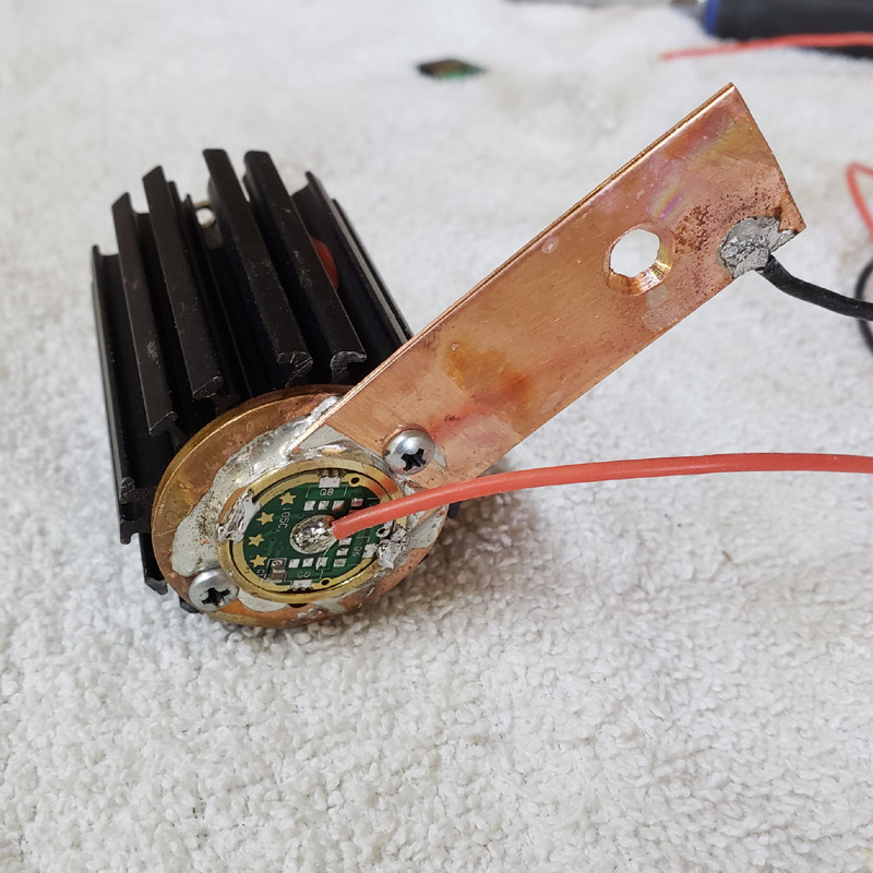
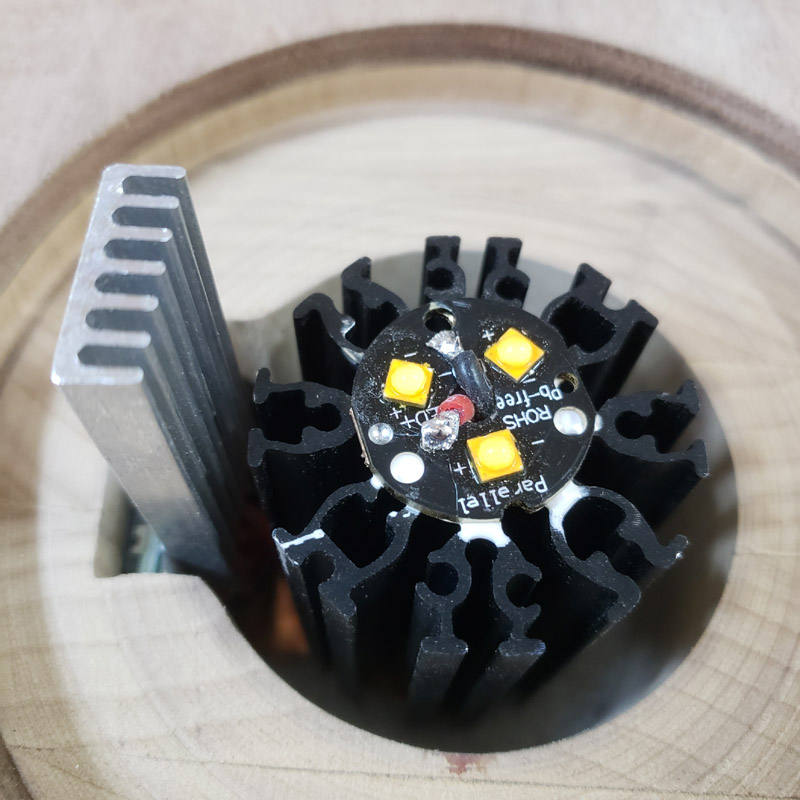
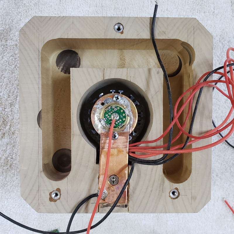
This morning I wired the mcpcb to the driver and installed the driver with a couple of leads left dangling. That is a Qlite 105C driver with only 4 of the 7135 regulators, for a max output of 1.5 amps.
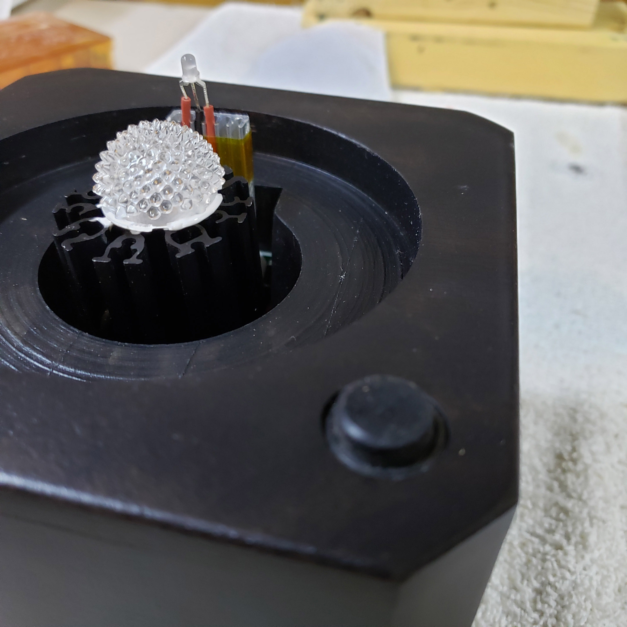
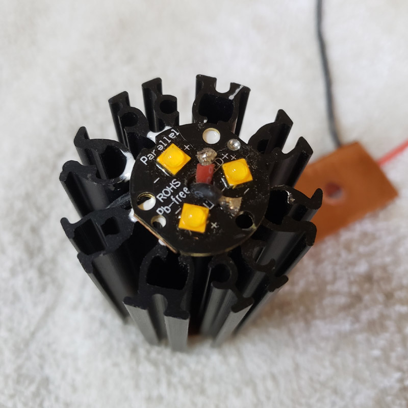
Here’s the photon end of it. A triple mcpcb from kaidomain and three XP-G3, 2700K LEDs that I reflowed myself. I know many do not like the G3’s because of the greenness. However, I don’t see green at all when these 2700K LEDs are used in a light-diffusing mode as compared to a more or less focussed or concentrated beam. I used a triple set of led’s, not for maximum output, but for slightly greater efficiency as compared to a single led at the same current.
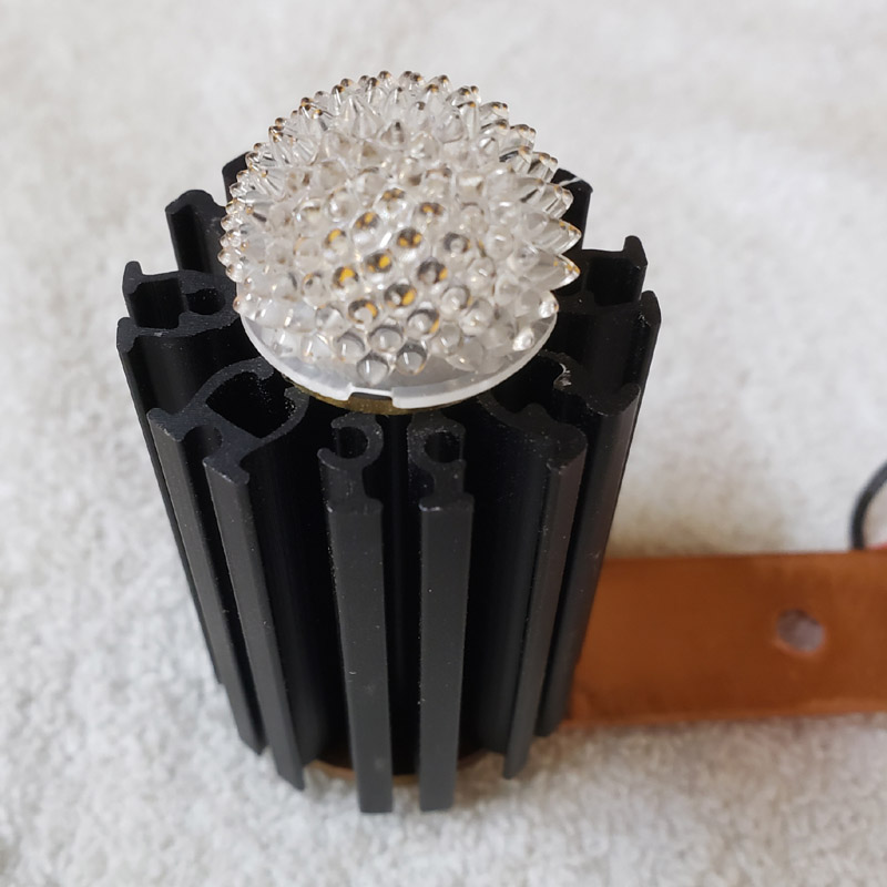
This lens/diffuser from Ledil will be cemented in place over the leds.
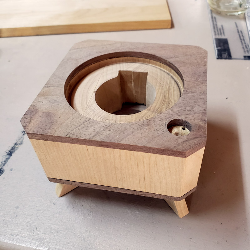
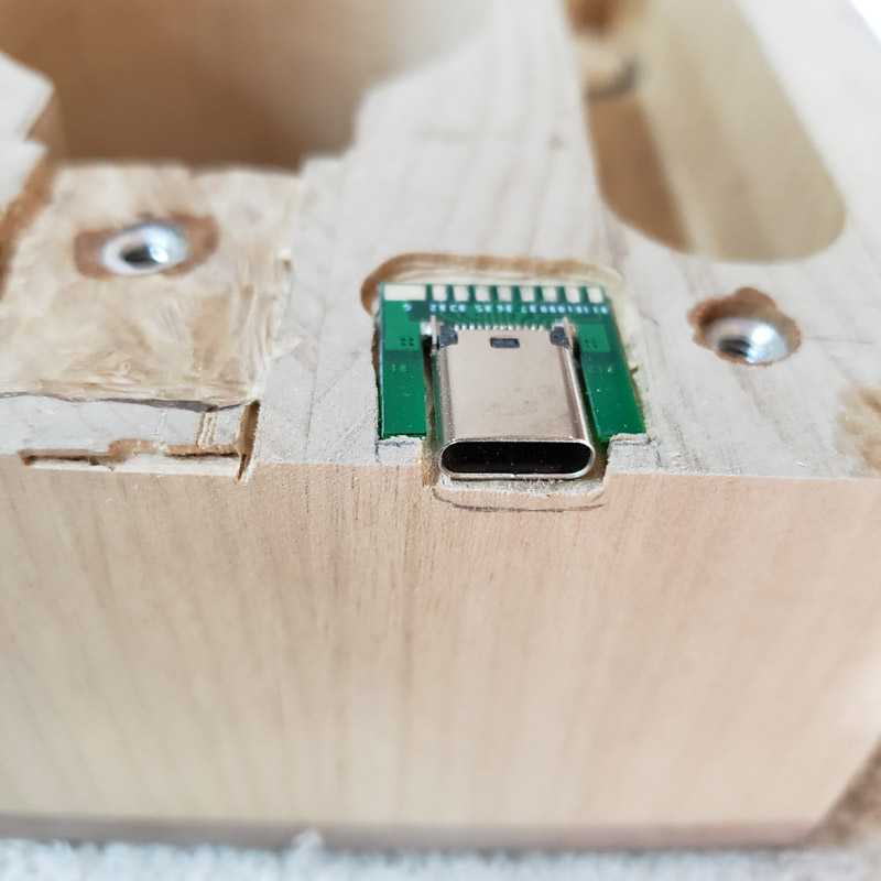
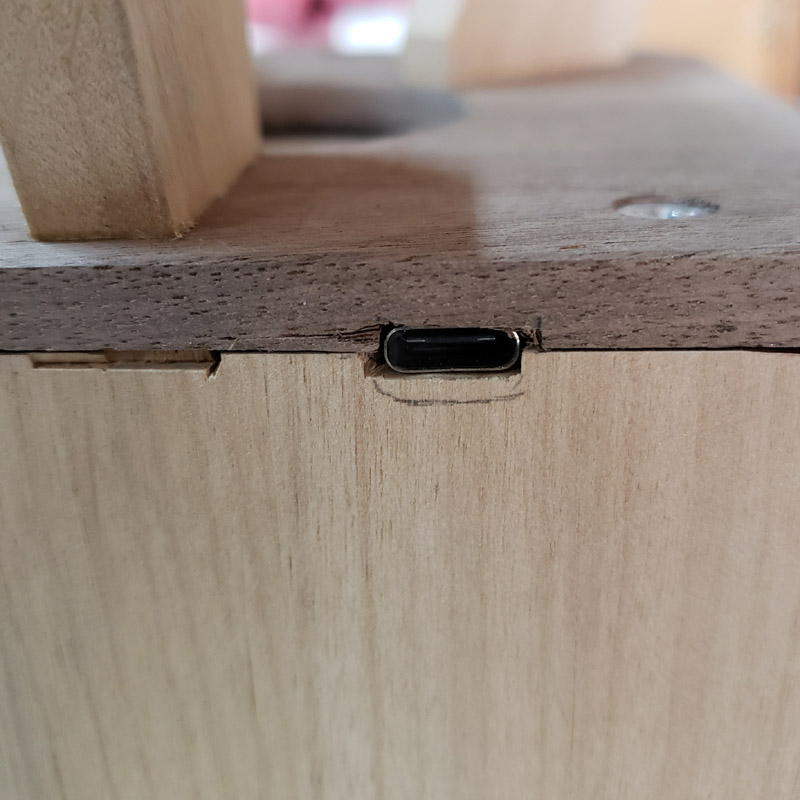
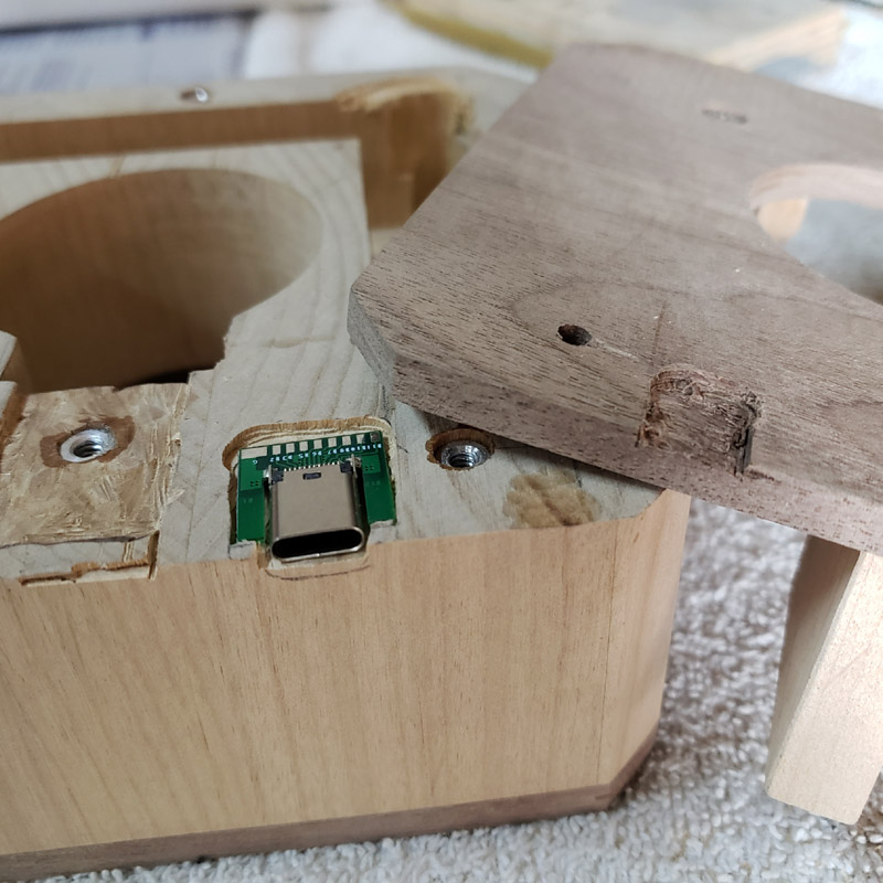
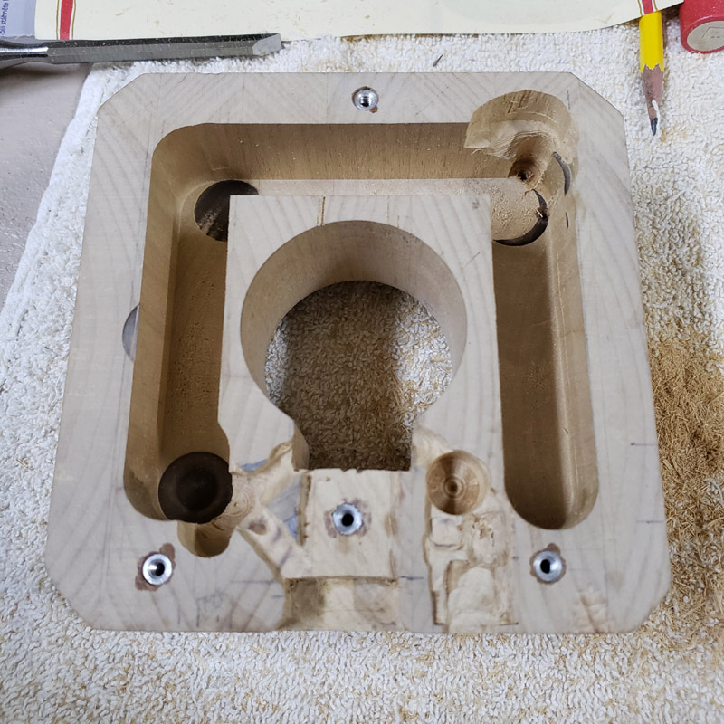
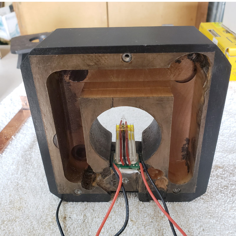
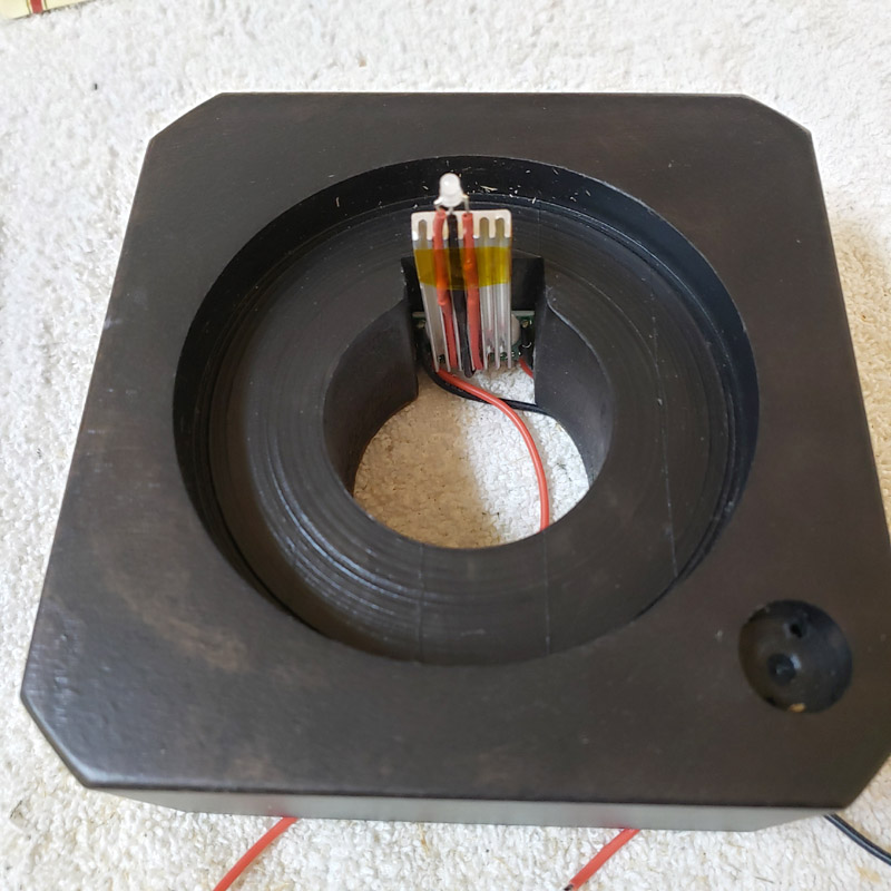
The charger with its heatsink fits into the slot and the heatsink with leds is centered in the well hole.
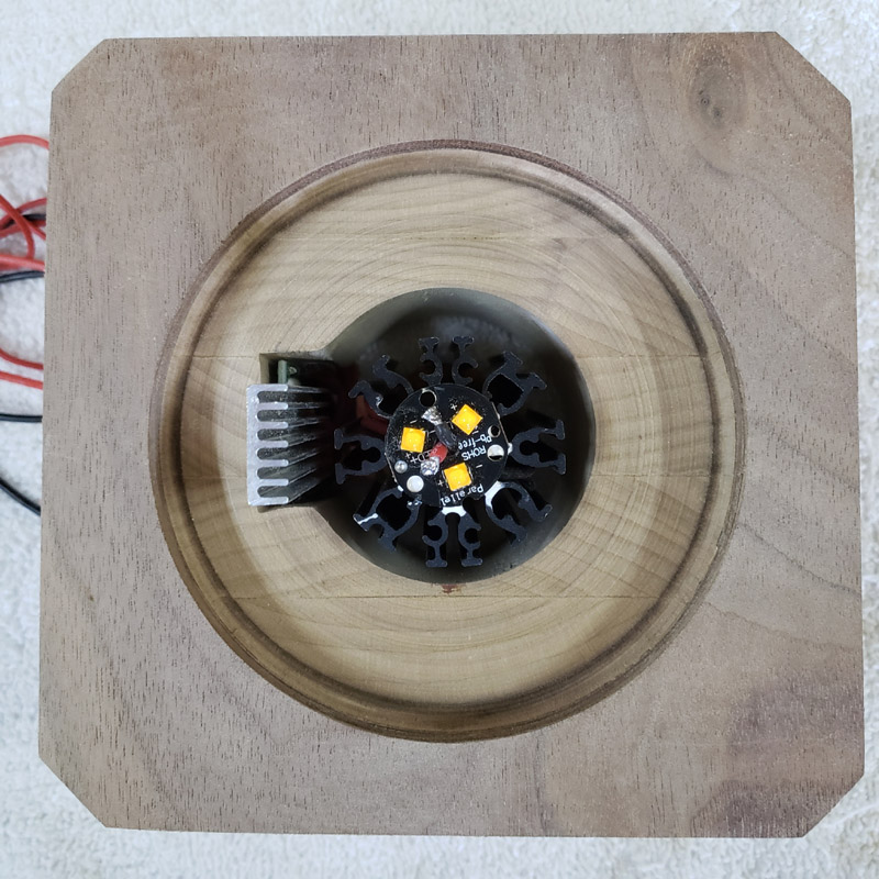
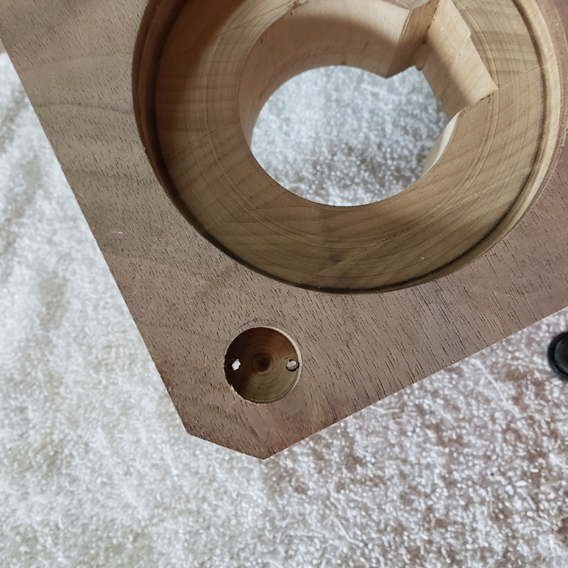
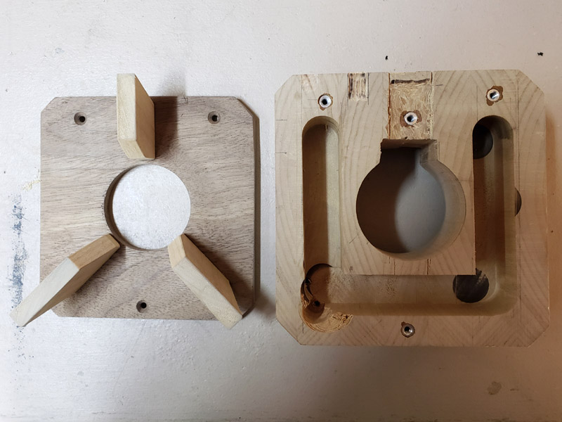
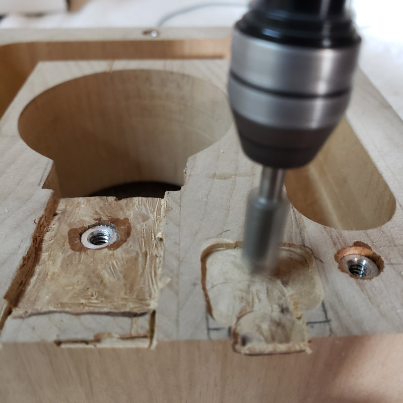
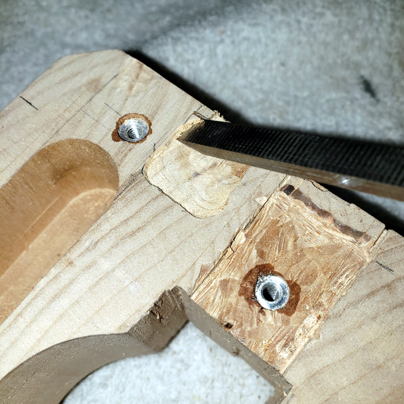
The view from the bottom. A 1/4” thick wood plate will cover the bottom and be secured to three threaded aluminum bosses that are pressed and glued in the block. There will be some grooves carved for the wiring.
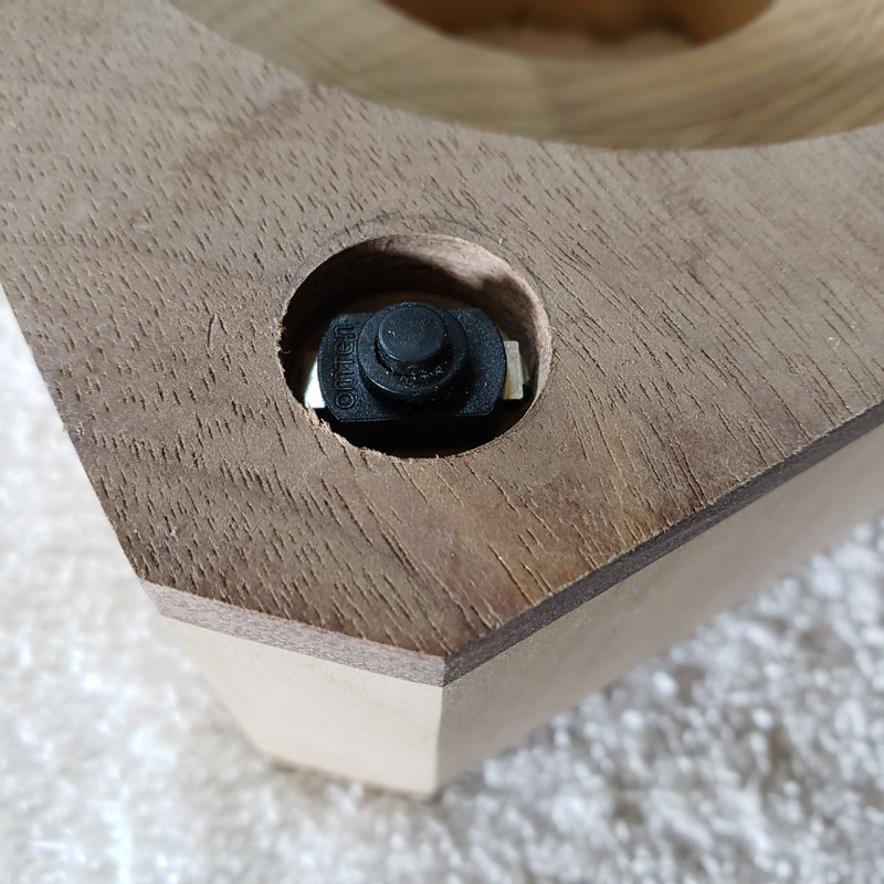
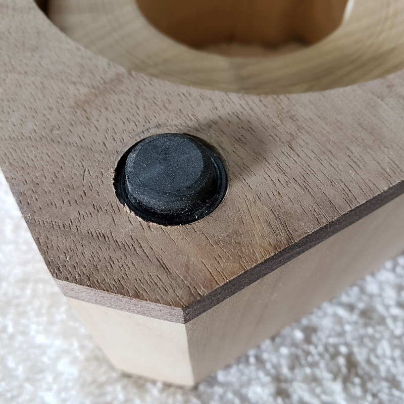
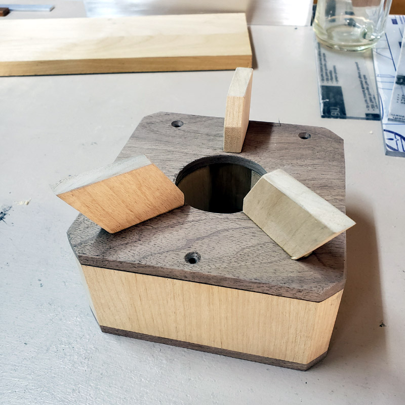
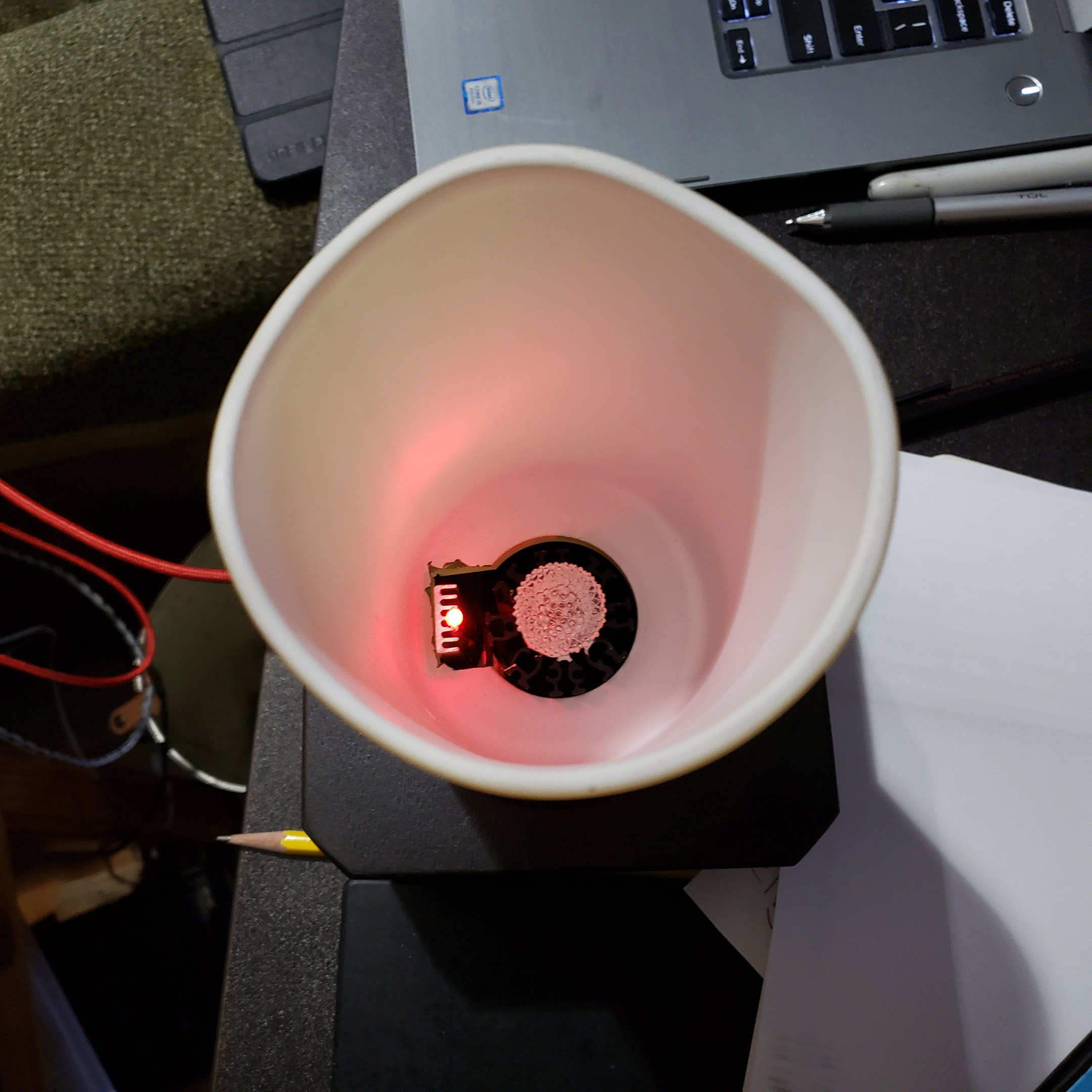
There will be some short legs secured to the underside of the bottom plate. This will elevate the block and permit air flow. The theory is that when being charged, or when the light is on, convection air flow from the bottom and up through the central well with the heatsinks, will provide cooling.
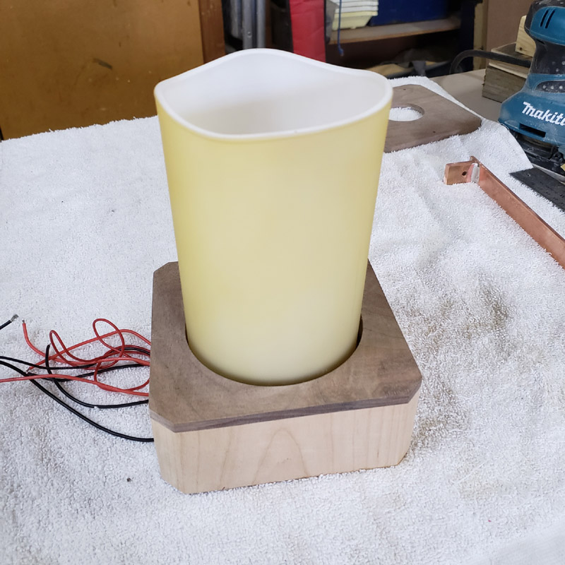
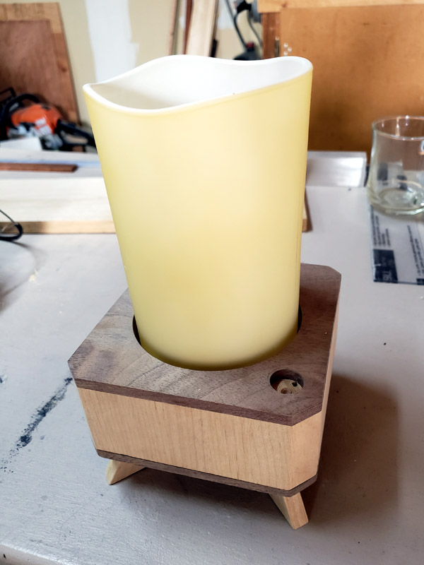
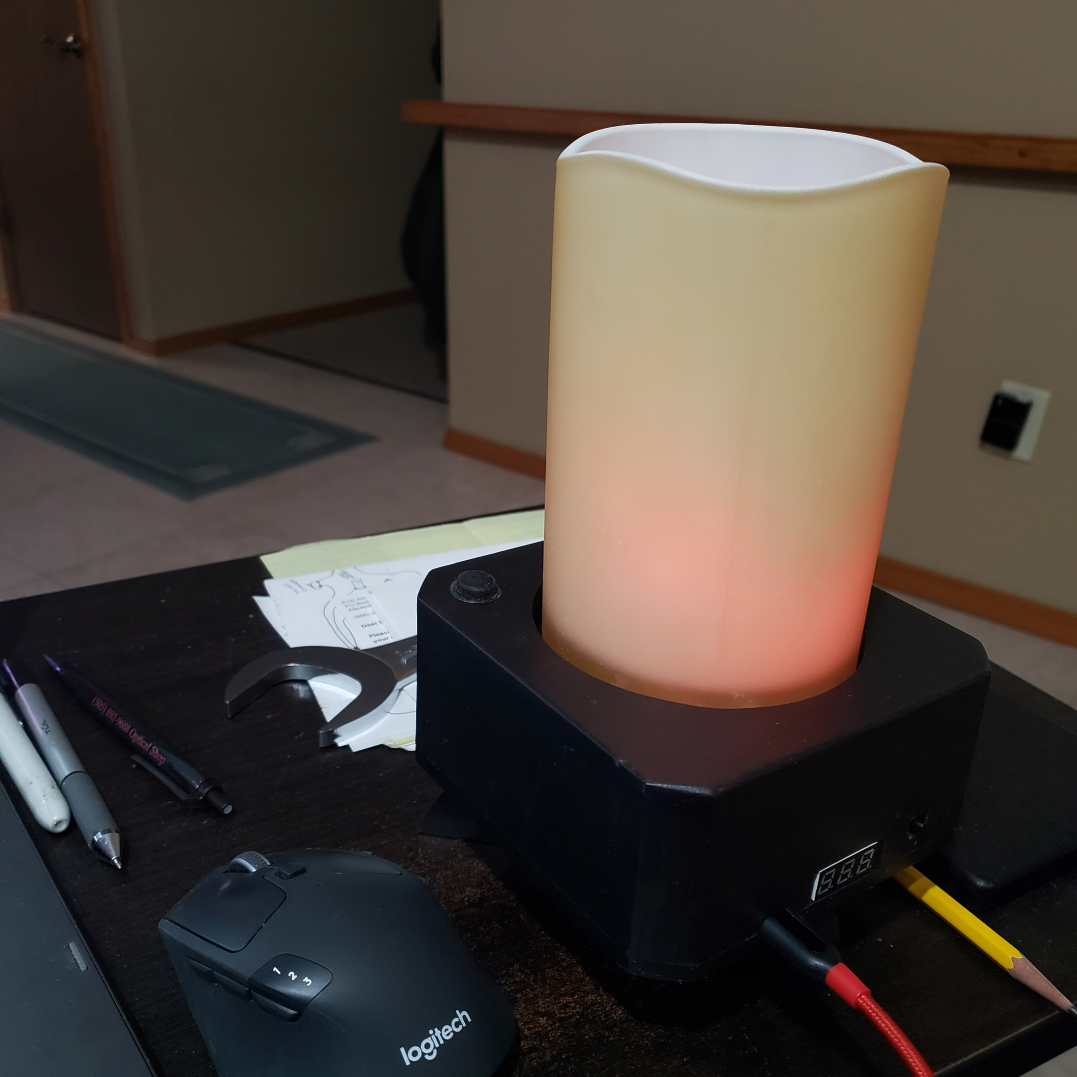
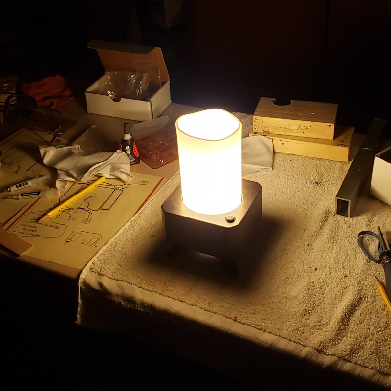
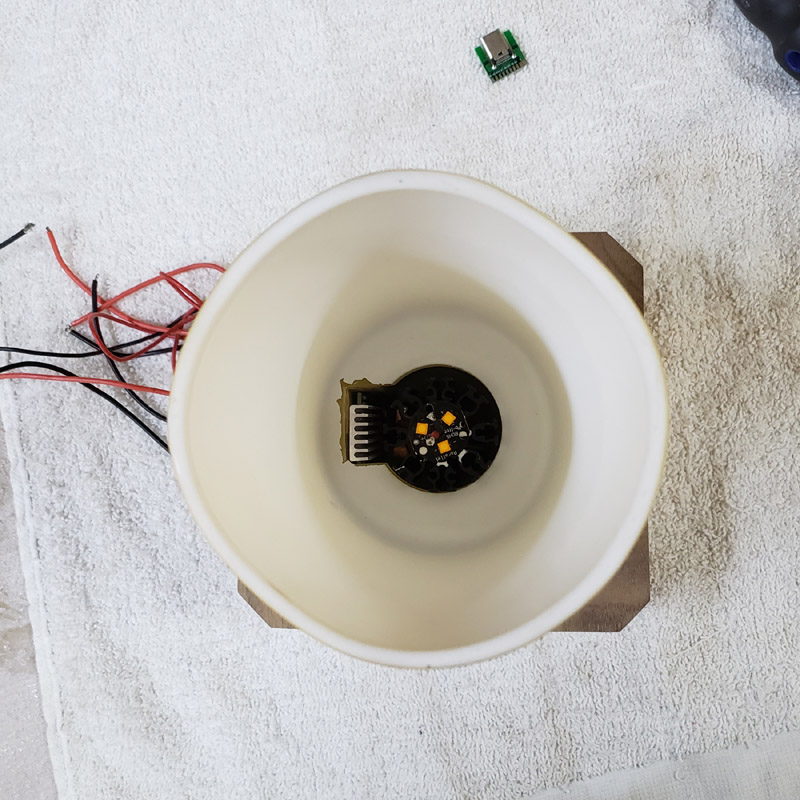
A view from the top, looking down with the glass shade temporarily in place.
And another perspective.