I really like the addition of the pakuda scales. Looks great Don!
![]()
Old hardened silicon rod (taken out from last year unused caulk tube) works great as well.
Two things…
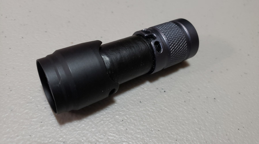
(1) I made a small mod. The diffuser lens on the rear end looked like a wart. I probably really don’t need so much side vision. So I removed it. In the dark the red tail light is bright enough as it is through the plain lens. So I removed the diffuser, countersunk the lens for the retaining screw and reinstalled the lens with a shorter screw. Now it can tail stand too.

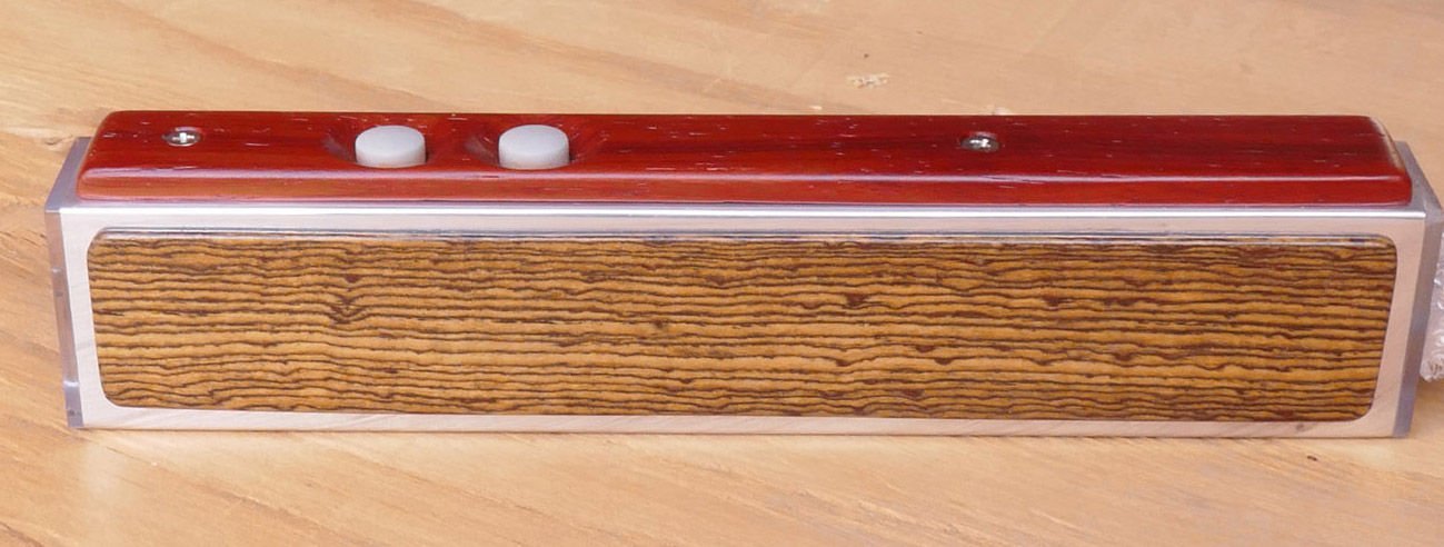
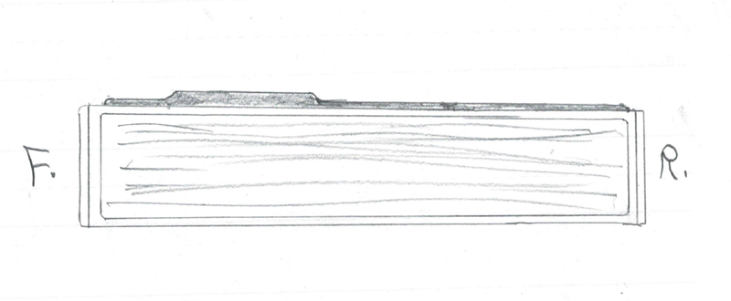
(2) I have a question. What is your opinion on this idea? I am wondering if the top strip would look better if it was thinner at the front before the switches and also thinner behind the switches. Below is a quick drawing to illustrate what I mean. I’m not sure that I could thin the front and rear areas down to the same thickness as the side skins. But the area around the switches would be a definite hunp. Thoughts/comments?
Go from this….
…to this?…
Amazing craftsmanship Don! ![]()
In between rain sprinkles I took a couple of night/beam shots. Snow coming tonight and I am getting over a cold and did not feel like ventuing any further. I also need to dust off the camera with manual settings rather than use the camera phone…. @ shots though, one with the front light and one with the rear red led on full and steady (blinky off).
Very floody elliptical Carclo optic used in the front. It is quite obvious in live real time that it spreads the light to each side and cuts off the up and down spread.

The rear is pretty much a mule, no optic

.
.
.
FYI, the hardware used to make this light, includes…
Front light: 3 - XP-L HI 1A led’s on a Noctigon triple mcpcb
Carclo 10510
Driver: Qlite 105C with 8 x 7135’s, the 380 mA version for total 3.04 amps
Firmware: Star off time, levels, 6, 15, 30, 50, 100%, plus moonlight
Rear light: 3 - XP-E2 red led’s on a Kaidomain triple mcpcb
Driver: Nanjg AK47A with 3 x 7135’s, 350 mA each. 1.05 amps total
Firmware: oldie by Toykeeper, “tail-light”. It has some blinkie modes and memory that holds last used mode including the blinkies. I like that for this light.
Switches: Two Omten 1288 reverse clicky
Charger: a TP5000 based 1 amp board with remote indicator red/blue led
USB-port: type C on a small pcb
Cell: Panasonic NCR18650B
Flat top with spot welded tabs added
Rear diffuser:
Ledil C15419 Zorya-Mini lens
Body tube: 1” x 1.5” (25 x 38 mm) 0.125” (3.3 mm) wall aluminum tube
Carrier/sled materials: copper, 3/4” (19 mm) wide x 1/8” (3.3 mm) bar for the main bottom section
Other copper: 1/4” (6 mm) thick bar scrap for front mcpcb mount and assorted 16 or 18 gauge copper sheet
2 - 17 to 20 mm adapter rings for the mcpcb mounting
3/32” (2.29 mm) lexan sheet for lenses
Fiber optic material, 5/32” (4 mm) diameter
Padauk and bocote wood for exterior and a scrap of pine for the internal usb port block.
Many of the components were previously used in some other project, or were bought just to have on hand because I was ordering something else and it was cheap to add a few switches, for example.
Your side view with the wood slimmed down looked ok in profile. It wood be a personal preference what you do though.
More details the better ![]()
I might be inclined to make a sort of ergonomic palm groove behind the switches on the top wood for the operating hand to sit in, leaving the front & very back level where it is if that makes sense.
Makes sense. I need a bar of modeling clay cut to the same size. Then squeeze it and see what/where to carve.
Maybe that will be V.2.0 I have enough aluminum tube, lots of woods, more leds and stuff….
Maybe I should have looked at using screws to mount the side skins/scales? Easy to change. V.2.0
I just made my very first flashlight video to illustrate the front and rear light outputs.
I am not a videographer by any stretch of anyone’s imagination. I seldom shoot videos; the last one I can remember (sandhill cranes) was something like 3 years ago.
I made this here at home in a subdued daylight illuminated room. In a dark room the auto exposure on the simple camera tends to brighten the lower levels too much and then the brighter levels all end up being washed out very bright points of light.
Anyhow here goes. The first video shows the modes and levels of the rear red light. The second the front white light levels. Rear light runs on 4 x 7135 regulators and the front 8 x 7135.


I enjoyed your videos MtnDon and I like what you did to the rear diffuser. The flashlight looks awesome to me!
Now that it is evening, I’ll try a darkened room video; white front light from off and then up through the 5 steps to full.

awesome work, ![]() :+1:
:+1:
it would look pretty good, imo, will the screws be still flush, or stick out?
I would leave enough wood thickness to be able to countersink the flathead screws so the head surface of the screws would be flush with the wood.
Great work ![]() I like the multi modes on the red light
I like the multi modes on the red light ![]()
Thanks to Toykeepers tail-light firmware. (I did tweak the flash timing a little with Atmel Studio, she TK did all the original work)
I admire your creativity and handcraftings skills, Don. This is again a great competition entry!
Well done on completing your build :THUMBS-UP:

Before I built this years contest entry I cobbled together a light to use for walking along dark country lanes at night. I used a Sofirn C8F that I bought a few years ago. I also used a Convoy S2 host I bought in 2015. The Sofirn was chosen for the white front light as it did not have a tail-cap switch. The S2 was chosen because it wasn’t doing anything better.
The idea I had was to couple the two lights at the tail caps. Below are some images. I did this a while ago and cannot locate the images I made showing the drilling, welding, etc. So for the making of the coupler, I hope my word picture will help.
I started with a 1-1/4” long piece of 1/2” black iron pipe; the type used to run propane gas fuel lines. I welded flat scraps of steel plate to each end. I drilled and tapped each plate. I think I used #10-32. The pipe ends were ground smooth with the end that was to mate to the S2 being ground enough to reduce the diameter enough to allow it to slip into the recess that is meant for the clicky switch.
The Sofirn C8F has a side switch; no tail switch. It just happened that the pipe piece was a very nice fit into the recess where a tail-cap switch would be if there was one. A hole was drilled through the Sofirn tail cap to allow a machine screw to be inserted from the inside, out to screw into my coupler. That did necessitate some fabricating for a spring contact.
The switch was removed from the S2 altogether and a spring contact plate made up for that end. I used a washer fitted inside the S2 tailcap and fitted the 10-32 machine screw from the inside of that cap into the other end of my coupler. Sorry that I have lost track of the images that cover these steps.
The S2 was fitted with a single red XP-E emitter and a 4*7135 driver with the same Toykeeper firmware I used in my entry for this year’s contest. The S2 body was simply loosened a half-turn or so to turn off the taillight. Tightening the S2 body into the tailcap turned the red light on. The front end used the stock side-switch. The Sofirn was essentially the same as it came with the exception of the tail cap hole drilling.
Cobbling the lights together like this did require the use of 2 cells, one for each body. I liked the utility of the light and did use it a lot. I had thought of using a shorty tube for the S2 portion with an 18350 cell. I grew the idea for my rectangular aluminum and wood scales light over time but never started and actual wotk until this year.
I just thought I would show what came before.