Outstanding!!
Looking forward to see results.
Did i mention i need 4 of them?
Outstanding!!
Looking forward to see results.
Did i mention i need 4 of them?
Thanks for the comments. Quick responses:
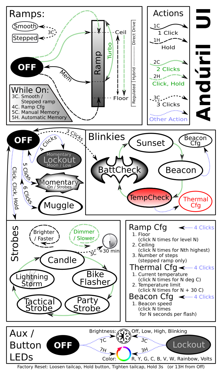
The lume1 driver was designed to use community firmware. Since the hardware is a little different, there are some small modifications that need to be made, but otherwise the goal is to allow the use of firmware such as Anduril, etc. As a result, the UI will be based on what firmware is used. Here's how it's implemented in Anduril: https://intl-outdoor.com/media/wysiwyg/D4V2/anduril-ui.png, as used in the Emisar D4V2 (though not in the FW3x yet).
This is not a problem to do, will hopefully have several different driver sizes in the future. At the moment, the focus is on the FW series of flashlights.
Not a problem either. What flashlights are good candidates?
Perhaps if this is popular, it may be possible to get a batch made; otherwise anyone should be able to build it themselves too like my other drivers.
I agree but surprisingly there are numerous folks here (including me) who just don’t get that part (build) like rest of you guys. Some stuff some of just can’t make it.
But i really do hope so that interest will be enough to make a batch :)
That’s very interesting.
What would be the best case scenario ballpark efficiency advantage vs the current FW3A linear driver ?
On the spring side, the ground ring and signal tube ring/trace are very close to each other. The host battery tube bore to the head and mechanical components like the signal tube, driver pocket, driver retainer ring, would need to be very precise in fit and alignment…I would think, from experience, it was one of the problems/draw backs of the NovaTac lights that used this same style spring side design…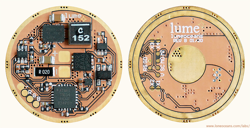
Best improvements can be seen when using low V_fwd parallel LEDs, together when battery voltage is high. For example, let's assume a medium brightness running 3 parallel SST20 LEDs, at a total of 1A current. This will have a V_fwd around 2.8V, consuming 2.8W total. At the beginning using a fully charged cell like the Samsung 35E, current draw will cause battery voltage to drop to about 4.0V. In the FW3A linear driver, the driver needs to drop 1.2V at 1A for a total of 1.2W. Efficiency in this scenario is only 70%. As battery voltage drops and V_fwd increases, overall efficiency would go up. Likewise if a different chemistry higher voltage cell is used when operating voltage is 4.1 or 4.2V, efficiency would be even worse.
In the lume driver, it will not be hard for the driver to be about 90% efficient (likely higher around 92/93%) at 1A, but that's a fair bit more efficient than the 70% of the linear driver. Not only that, power dissipated by the driver drops from 1.2W to 0.31W, saving 0.88W. This should also allow the flashlight to run cooler and marginally more efficiently (for the LED), for the same lumen output. In this case, about 28% efficiency improvement. Hope this gives a good idea.
Yes, this is true, but from what I've seen in the FW3x and FW21 flashlights, the tolerance is very tight and the flashlight is very well built; I don't see any mechanical issues and clearances are actually very generous. Again though, this concern is perhaps more related to the FW3 design; the lume topology is easily adapted to all sorts of other driver sizes and mechanical designs.
Following - interested in efficiency - but would like to see in a slightly larger flashlight with more thermal mass to be able to run on high/turbo for extended times. Maybe a Convoy L6 with short tube and side E switch. Another one for small boards for L shaped headlamps, skillhunt/sofirn SP40/convoy H1. Although built in charging would be odd for the SP40. A fully regulated output on a headlamp would be nice.
Wow, very impressive! The ultimate in regulation. I think it’s so cool that one person with your skills can make something that is very desirable but almost no flashlight manufacturers offer.
Another example with triple XPL HIs whose voltage is 3.0 to 3.1V at 3A combined current. With a high capacity cell like the GA the linear driver will stay in regulation for almost the entire time (around 3Ah). Near the beginning the driver efficiency is worse (77) but over the full discharge of the cell it is average of about 85 efficient.
At 1A total the average efficiency over the full discharge would be about 78%.
I am in for at least 10 of these if there’s a run. I will change out all of my FW3X and FW1As.
I’m also in for 7 for my Skillhunt headlamps if that size gets run.
Looks amazing!
Totally in for a few of these at least for my FWnx lights as well as any other that it can be adapted to!
What is the power capability of each of the r g b outputs? I’ve been thinking about doing a build with a set of ‘aux’ E17As in 2000k, 3000k, and 4500k for use as a variable CCT mule/diffuse beam. If I could manage 100lm on a channel that would be amazing. More is obviously a bonus. So that’s mean ~1W and ~300mA. If the MCU drives these then that seems unlikely.
Either way, great work. Sign me up. Take my money. Thanks!
EDIT: A brief look at the traces and the datasheet suggests to me that with the layout as-is, reaching such current/power levels on the RGB pads won’t be possible. If I’m understanding guessing correctly, these pins (2,3,4) are acting just as MUX switches? Is there PWM or are current limiting resistors the only brightness tuning component? If I’m thinking about this right, then I’d need to adapt this with additional passive components ( maybe a multi-channel FET) to be able to handle the load.
Great idea. I’d add a jumper on the component side to configure if e-switch signal should be taken from signal tube ring. That way it could be easily adapted to other e-switch hosts.
Is it necessary to use buck-boost? It is more complicated, and less efficient than buck.
At low V battery have small amount of energy. So efficiency of buck may could give more than work at low voltage with buck-boost
Thanks! There are currently no plans for a group run though, but we'll see..
In this case, the RGB channels are driven directly from the MCU and are only meant for dim aux lighting; again the original intent was based on the use case presented in ToyKeeper's Anduril and similar firmwares. It's not difficult to use those pins to control something else (small fet and resistor, or it's own 7135 etc), but this will probably not be the main focus of the lume driver boards. Design will be open sourced and you will be free to modify it to your own purposes, though you will need to adapt your own firmware too :).
Thanks, but there are no plans to add a jumper for this specific board, since this board was optimized for the FW3x, and may not fit many other flashlights. Other E-switch hosts will do well with a different board design, perhaps in the future. Design will be open sourced, and anyone will be able to design their own for their custom use :).
Thanks! However, Buck-boost here is no more complicated than a buck, does not use any additional components in this case, and in the targeted operating parameters, only very slightly less efficient for a buck with similar resources (but more efficient than cheaper non-synchronous bucks for example, or cheaper synchronous bucks). Buck-boost is a necessary however, and should always be done in this case as good engineering design. In most scenarios, this BB will be operating in Buck mode, but take for example the scenario when temperatures are sub freezing, battery is a little old, and isn't completely full - this is a use case for me such as when I'm camping... boost mode operation is required then.
It is true that there are many more dedicated buck regulators with small footprint on the market with high current capabilities, however it's still a little bit of a conundrum, as the higher the input current increases, the lower the battery voltage will be, necessitating the need for a boost even more. For higher power requirements, I'll refer to the GXB series of drivers. Finally, there are also many inefficiencies in flashlight systems, especially as flashlights get older (contact resistance being very significant), which Buck-Boost operation will hopefully help mitigate.
Wow, there was longing for a driver capable of both high outputs and high efficiency while having BLF UI. And your driver delivers that. I’m sure there will be many people interested, especially once it’s available in a more standard format as well.
The lack of RGB aux has kept me from buying FW3A - you just added this while improving efficiency. Great. ![]()
Though for me the sense resistor in series with FET is actual misfeature, I have a light that steps down in less than 10 seconds and I could easily go with even less than that. And 200 mV drop at 10A is a lot.
I hope these will be more available than the previous drivers…
This. Nice work again. ![]()
Regarding the sense resistor, true, it's not something I'm too happy about either; perhaps I'll figure out a better solution without adding another big FET (which I guess is possible, but not very elegant..). However, I think considering how fast the FW3A begins stepping down at Turbo, perhaps with a less bright turbo, it may be possible to have the light running at this lower turbo mode, but for a longer period of time. Maybe less wow, but could actually be more useful? I think some very low V_fwd LEDs may benefit from this too. I hear that typically running some Nichia 219 LEDs require a change in the FW3A firmware to run turbo at 50% duty, or for the user to use a lower-drain battery to mitigate.
I’d definitely be interested in a couple of these for my FW3A’s, and also some in other sizes if they get made, SP40, A2S etc.
Some users want dimmer but longer turbos, some want them brighter but shorter. There is no duration that’s good for all. Myself I’m one of the more extreme bunch, for me even 5s would be enough while many consider sub-10-second turbos to be too short. Some don’t want turbo at all and want the highest mode to be so low to last until the battery is empty.
I don’t believe that increasing or decreasing flashlight power output makes it more useful - it will always be more useful to some yet less useful to others.
And that’s why I think that firmware is a better place to manage that. Because it’s easier for users to adjust it to suit their needs. As of now it still requires re-flashing. Programming pads make it easier but it’s still not for everyone.
Maybe one day it will be possible to just configure Turbo output like it is possible to change ramp max now.
May I ask what buck boost IC you are using? When I was looking through Mouser for a design of my own I didn’t find anyone that could do 3A.
Edit: No worries, I found it. I looked at that one but within the first three lines of the datasheet it stated output current 2.5V to 3.3V as 2A. I didn’t read the part under the description where is stated “output currents up to 3A are supported”. I ended up selecting a different IC with somewhat similar ratings for mine.
Great Loneoceans!! It is always a pleasure having news of your work.