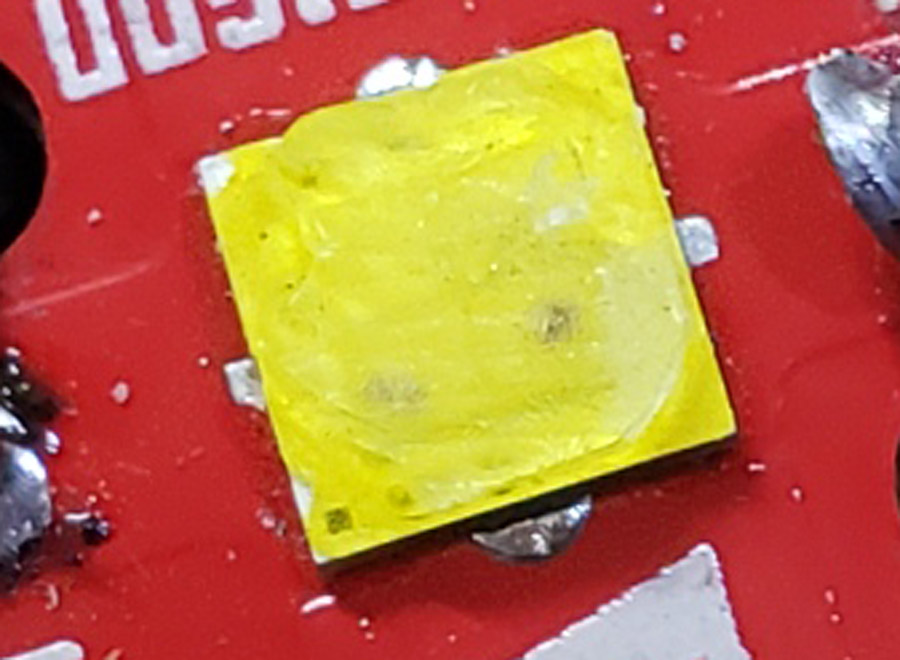
Not a great shot, but the little dark spots never used to be there.
I tried to limit the current to the led with smaller wires than I would normally use but after about 15 seconds it flared brighter and bluer and then blinked out.
I could try another xhp50.2 but that may be pointless. My other “on hand” choices are an XP-G3 (3000K or 5000K), a Nichia 319AT (4000K), an LH351D (5000K), an XP-L (unknown). Hmmm. Maybe the XP-L considering that the driver is an FET+7135 variety?
Woah it takes a lot to kill the 3v 50.2. Maybe yours was defective? Matt Smith tested it to like 13A and it lived giving over 3100lm. I run mine in my zoomie (5000k) on a vtc6 and fet driver fine. Maybe try the xp-l or samsung. That’s the only other emitter I’d think could handle the current.
The other XHP50.2 I have is on a 16mm noctigon, just like the first. I’m wondering about changing the mount from the brass pill to a copper slab, and silver soldering it to the base copper strip. Maybe the brass was not conducting the heat away well enough? Then I need to make/mod a mount for the driver. [scratches head]…. Space is tight.
Or use the XP-L or the LH351D. I have a single mcpcb I could reflow either onto….
And I discovered I have an unused 20mm triple LH351D…
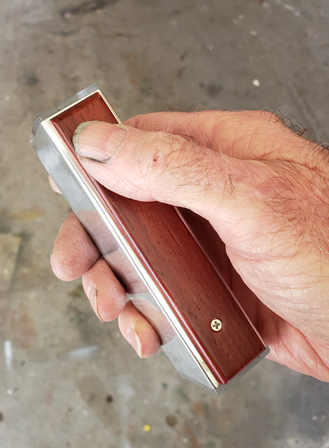
Meanwhile I have been polishing the aluminum tube.
I was looking at your setup and as one who has done some crazy stuff with junk I had lying around for heatsinking in tight spaces, I can’t see a reason why your 50.2 died so fast. Thats a good mcpcb and the thermal path is good enough for short bursts on turbo. I’ve only killed one in my day and it was because I shorted the driver. That emitter should have lived, especially since it’s hot a super low IR cell and you did have current limiting. Maybe try a different battery with the xp-l and 24 gauge led wires. I really like the 319 with the hex die! Best beams you can get I think.
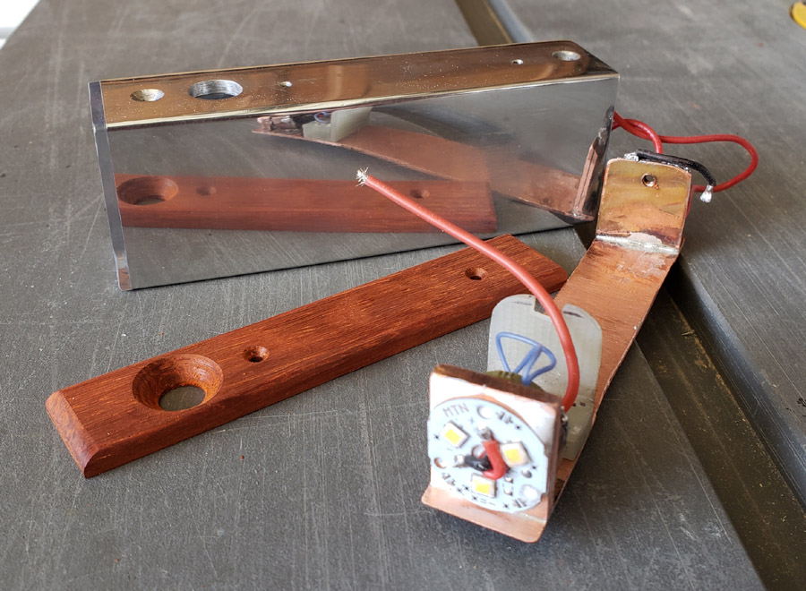
I’ve been looking it over and am thinking of slicing the pill in half, removing the front portion and replacing the front portion with a strip of 1/8” thick copper; 3/4” x 3/4”. That can be silver soldered to the copper base strip and the remaining brass which will still mount the driver. Then use the other XHP50.2 that I have. I cut a little off the front of the switch mount to give a small amount of extra space to fit in the driver. Nothing like a challenge.
That would help heatsinking for sure. I used a brass C8 pill as a driver mount/heatsink before. Just sanded the front flat and soldered it to a 3.5mm piece of copper mounted to the heatsink. Was enough to tame a sst40 direct drive. I think you could make that work. I’ll be interested to see how it works.
After some thought, I decided to not use an XHP50.2 but instead to run a triple Samsung LH352D @4000K I did improve on the heat sinking by replacing that brass pill and making up a mount for the mcpcb from a piece of 1/8” copper strap material.
I cut a brass do-dad to mount the driver to. My first attempt at soldering it all together had problems. There are three pieces, the copper base strip, the copper mcpcb mount plate and the brass ring for the driver. They kept sliding around when the silver solder would flow. So I made up a clamp with an aluminum bar and a black oxide coated machine screw. The solder doesn’t stick to either. Here’s a picture or two. Not visible is a black oxide screw that is holding the brass ring in place on the copper base strip/
Once soldered and cooled I removed the clamping apparatus.
I spent a few hours over the past couple of days polishing the aluminum tube. I made the top wood strip from the cutoff from the project for the 7th O-L contest. It will secure to the aluminum tube with two 2-56 machine screws. The wood strip will hold the switch boot in place and the recess makes accidental activation less likely.
Next, a little more polishing and side skins. Then a reassembly of all the parts.
Finished the polishing today and reassembled the light. Everything works as it should!
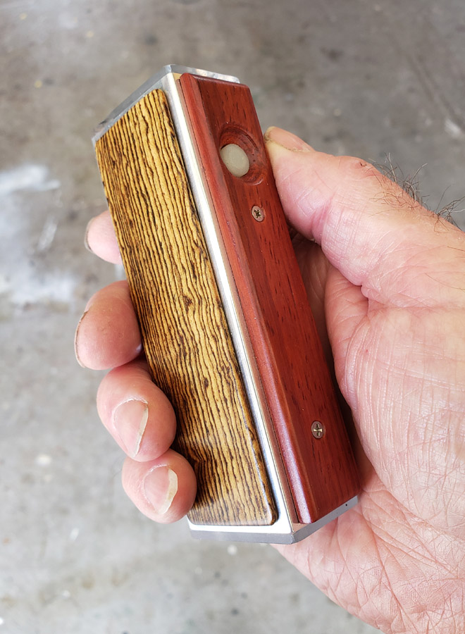
I have not yet finished the wood side skins, but did cut the strips. I do like the blingy look of the polished aluminum. But also like the toned down appearance with the side skins. I do believe I will complete this with the two side skins, but for now here it is….
The switch recess is deep enough to make accidental operation unlikely. The recess may be a little too deep, though. I intend to use it for a day or two before deciding. The wood will be easy to sand thinner, but that is irreversible. If I go too thin then I need to make a new plate.
Thank you. It looks nice sitting on the end table in the LR. The 4000K LH351D’s are proving to be a good chocie too; nice color of light for indoor use.
Yes. With it being an e-switch it does not take much to click it. If this light had a mechanical clicky switch like the longer light then the switch boot and button could be higher. Being recessed this much does make triple-clicking for the battery test, or quad clicks for lockout more difficult though. I think it is a decent compromise though.