For programming adapters, I just used the AVR JTAG ICE for the first time. It’s similar in appearance and price to a AVRISP. It worked well.
In Anduril, it’s incredibly easy to switch pins thanks to the “hwdef” (hardware definition) files that contain pinout info for a specific driver.
Now that Anduril is working, I plan on trying one of those PIC adapter boards soon. SC31B? FC11? TS70? Not sure which should be my first candidate. Hmm… After finally getting it ported over, my modding interested has finally piqued again.
Those JTAG ICE programmers are pretty expensive. There is a little five dollar clone on aliexpress that seems ok but shipping to Canada is pretty horrible right now.
Where you able to use the hwdef files without modification? That would make things easier for someone with programming skills as bad as mine. Solving invisible problems gets frustrating and I usually end up with the same two questions. Why can’t they do anything normal and how can I make a four pound hammer a solution to the problem.
PIC hunting seems fun though. Can’t wait to replace high, low, flashy with anduril.
Yeah, sorry… I was referring to the ~$5 clones, like what is referred to in this guide
But if you’re going to use Atmel Studio (or compile avrdude on your own), then an Atmel dev board like the ~$8 416 Xnano is perfect.
Hwdef files do need modification, but that should be expected. It’s a different MCU, so a different layout.
Part of what I’m curious about /hopeful for… These 1 Series chips come with up to 32KB of memory. If TK can fit Anduril in 8KB, what can she do with 4x as much space?
Hey…nice find with that jtag ice
The best combination of simple and cheap that I’ve seen so far.
Does it allow debugging 1 series chips or programming only?
Not that I’m aware of, though I haven’t researched that.
I have used the 416 Xnano to debug in Atmel Studio. That worked very nicely! You just disconnect the onboard MCU and then you can use it as a programmer/debugger for any of the newer chips (using the onboard mEDBG).
1+ for the 416-Xnano. Pros are that you can power the target with 5V from the Vref pin on the programmer side, has a CDC TX so you can talk with a terminal, user button and led, plus all the pins are labeled on the device side silkscreen, very nice and easy way to get going.
I also have the 817 Xmini, which is very nice but overkill if all you want is a programmer / debugger. Real nice dev board though. And still inexpensive.
It doesn’t sound like moving I/O between port a and port b is very hard so that’s good.
I once asked TK if she’d prefer to abandon the 85 altogether and just use a new one series with an adapter board but she prefers to keep the 85 for backwards compatibility. The amount of work she does to squeeze everything onto the 85 seems like a lot, especially for a volunteer. I’d like to she what she could come up with if she had IOT connectivity to work with.
You don’t need the LED driver circuit to develop the firmware. For most parts of the development an oscilloscope or logic analyzer is enough. Or hook up a small LED with a current limiting resistor to a free pin.
For initial firmware development and debugging, SammysHP hit it on the head. But also…
These Xnano and Xmini dev boards give you the ability to disconnect their onboard MCU. You can then wire the programming/debugging chip on the Xnano/Xmini to any of the 0-Series or 1-Series chips thru the 1 wire (plus power and ground) UPDI (unified program and debug interface). So you can actually debug code running on an actual flashlight driver.
Boy, I'd love to get into this development setup, if only I had the time. 32 KB is a whole lot, and would really like to see what can be done with 2 switches and multi-channel, multi-LED. If only I had more time.
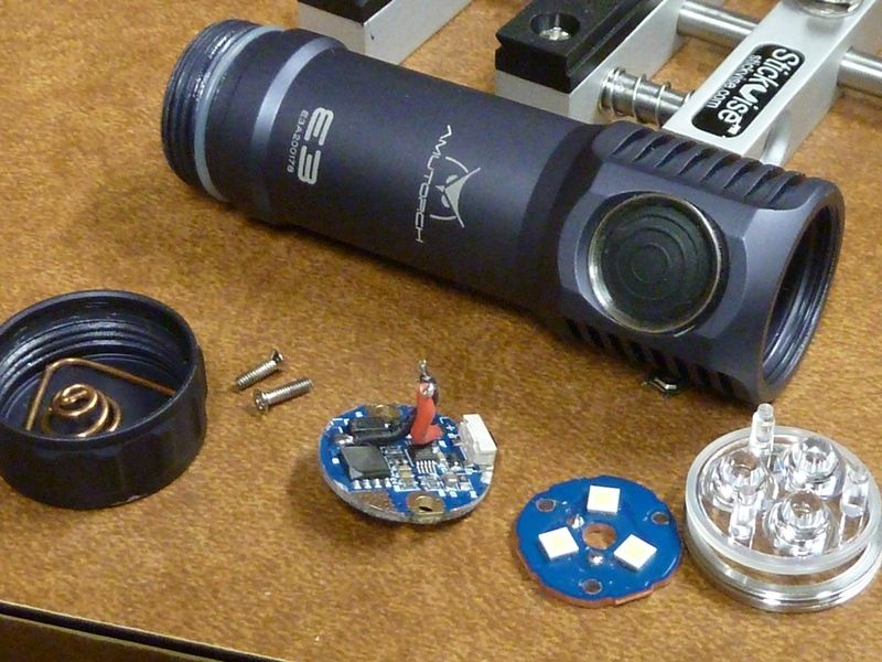
I got in a Amutorch E3 - 21700 triple LED, standard MCPCB, std triple optics. It's light weight and compact, but they made the cavity above the driver extremely small - 2.4 mm clearance over the driver, so I can't piggyback a small board in. Only option is driver replacement and it's got 2 screw holes for mounting - great idea really but no std OSHPark driver will fit, plus with a board mounted switch. Love to build up a OSHPark board for the E3 with this MCU.
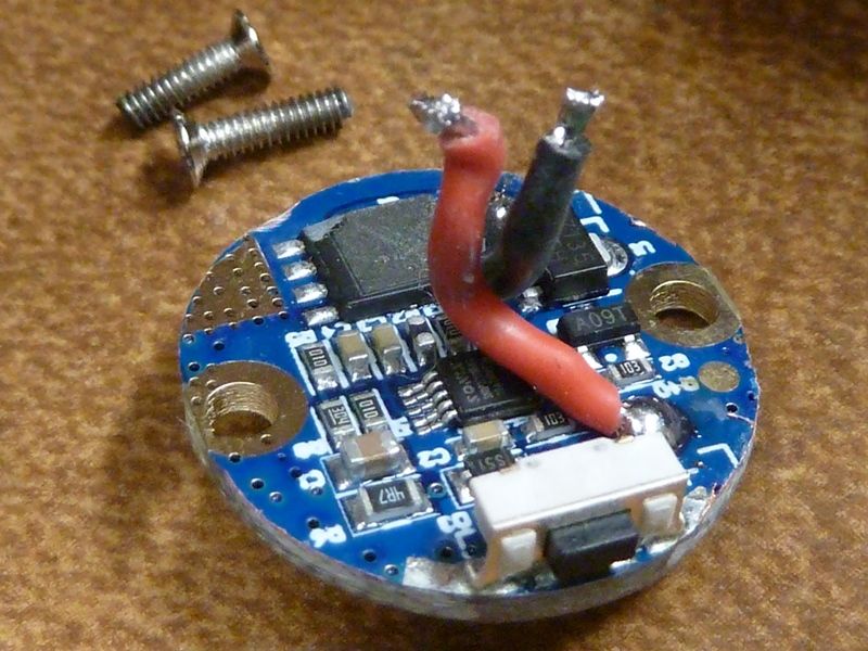
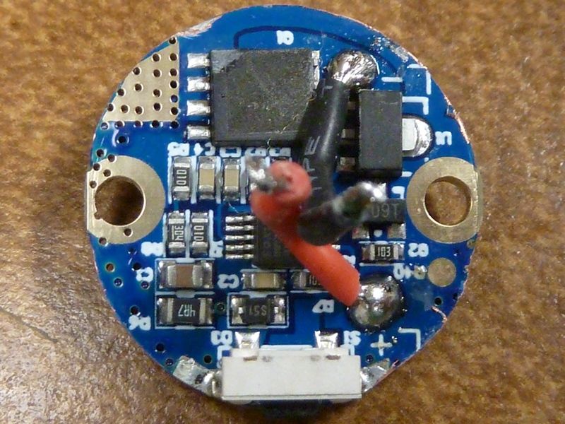
Actually CerealKiller did a OSHPark board with a driver mounted switch and I've used it a couple times. Not sure if I have pics - will take some and post.
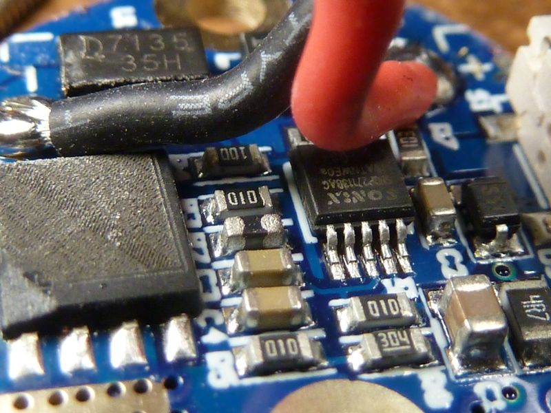
I already took pics but didn't post. It's a classic FET+1 design with the FET markings rubbed off, 10 pin MCU - not sure what it is, but here's the manufacturer's page: http://www.sonix.com.tw/category-en-947
Ohh, I do like how compact that looks. Appears to be a good candidate for a driver swap. Anybody have one of these that they want to get rid of? I wouldn’t mind putting a driver together for it.
Hhmm. Maybe you can have this one. Neal gave it to me, actually, with my last order. It's a one piece shell, but the switch is a bit squishy - too far off from the mech switch. I told Neal, he said he'd pass it along.
thanks for sharing your ideas, I’m reading with interest what you are up to here and I might as well join in with a board or two.
It’s not that my wishes exceed the 85’s 8kB. I customized FSM/Anduril to my liking within 8kB, but I would very much like to have the possibility to have more resolution for PWM. Especially in the moon region and at the seams of the PWM channels.
If I read the datasheet right the 1616 supports more than 8 bit PWM, that would be THE argument for me to migrate.
I’m already converting a brd for a future project and like the idea of the 20pin 3x3mm versions best, hence my eye is on the 1616.
My next obvious question now would be: Which function at which pin? Where should the PWM go, where the switch pin, where the indicator LEDs?
Or does the multiplexer allow to connect every pin with every feature? And do all ports allow for higher PWM resolution? I saw gchart using port B (PB0-2) and adding the aux led on PA1, which I presume was more or less random. And which function would profit from the energy efficient Timer/Counter D (pwm, switch, indicator)?
I welcome your input. I got some spare time and I’m looking forward for some board design. But 600+ pages of datasheet is quite a burden for me, and I even did not fully fathom this multiplexer thing, yet.