Adventures in TinyAVR 1-Series

Boy, I'd love to get into this development setup, if only I had the time. 32 KB is a whole lot, and would really like to see what can be done with 2 switches and multi-channel, multi-LED. If only I had more time.

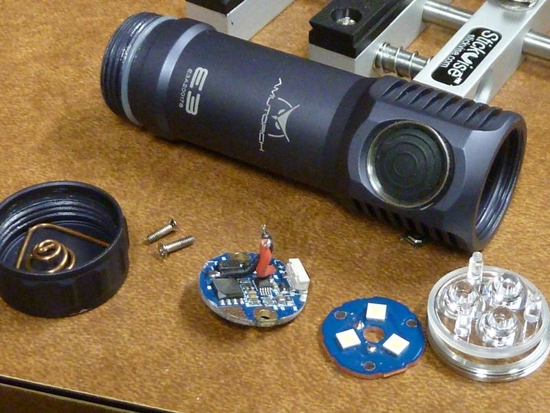
I got in a Amutorch E3 - 21700 triple LED, standard MCPCB, std triple optics. It's light weight and compact, but they made the cavity above the driver extremely small - 2.4 mm clearance over the driver, so I can't piggyback a small board in. Only option is driver replacement and it's got 2 screw holes for mounting - great idea really but no std OSHPark driver will fit, plus with a board mounted switch. Love to build up a OSHPark board for the E3 with this MCU.

Man, driver mounted switches can be a pain. Means you usually need a custom one-off driver. Got pics of the driver?

Actually CerealKiller did a OSHPark board with a driver mounted switch and I've used it a couple times. Not sure if I have pics - will take some and post.

This is one: https://oshpark.com/shared_projects/yoNxPZWi, this is his whole collection: https://oshpark.com/profiles/Cereal_Killer. I used this one: AT-008_V2

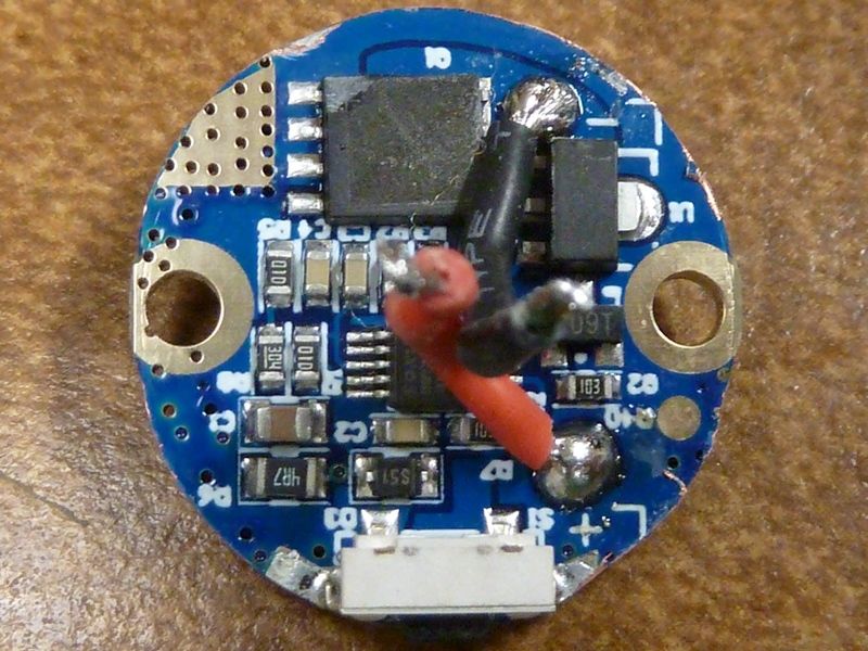
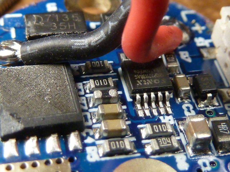
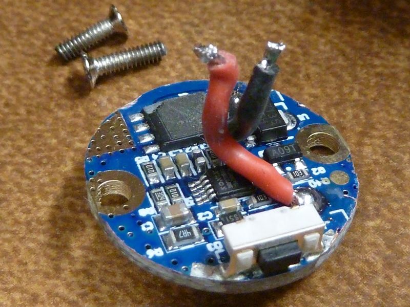
I already took pics but didn't post. It's a classic FET+1 design with the FET markings rubbed off, 10 pin MCU - not sure what it is, but here's the manufacturer's page: http://www.sonix.com.tw/category-en-947

Ohh, I do like how compact that looks. Appears to be a good candidate for a driver swap. Anybody have one of these that they want to get rid of? :wink: I wouldn’t mind putting a driver together for it.

Hhmm. Maybe you can have this one. Neal gave it to me, actually, with my last order. It's a one piece shell, but the switch is a bit squishy - too far off from the mech switch. I told Neal, he said he'd pass it along.

Naw, I don’t need you to let go of yours Tom. Half of the reason for acquiring one would be to put together a board you could play with!

Hi all,

thanks for sharing your ideas, I’m reading with interest what you are up to here and I might as well join in with a board or two.

It’s not that my wishes exceed the 85’s 8kB. I customized FSM/Anduril to my liking within 8kB, but I would very much like to have the possibility to have more resolution for PWM. Especially in the moon region and at the seams of the PWM channels.

If I read the datasheet right the 1616 supports more than 8 bit PWM, that would be THE argument for me to migrate.

I’m already converting a brd for a future project and like the idea of the 20pin 3x3mm versions best, hence my eye is on the 1616.

My next obvious question now would be: Which function at which pin? Where should the PWM go, where the switch pin, where the indicator LEDs?

Or does the multiplexer allow to connect every pin with every feature? And do all ports allow for higher PWM resolution? I saw gchart using port B (PB0-2) and adding the aux led on PA1, which I presume was more or less random. And which function would profit from the energy efficient Timer/Counter D (pwm, switch, indicator)?

I welcome your input. I got some spare time and I’m looking forward for some board design. But 600+ pages of datasheet is quite a burden for me, and I even did not fully fathom this multiplexer thing, yet.

Thanks
HQ

HQ, good to see you around!

Timer/Counter A and B are both 16 bit. Timer/Counter D is 12 bit. The advantage of using TC-D is the ability to have clocked separately from the main CPU clock. While it could have many applications, I feel like the main benefit for us would be to use the 32 kHz ultra-low-power clock for the main CPU and then we could still use PWM at a high rate without the CPU sucking up a lot of current. For the sake of comparison, say you wanted a 10-bit PWM (1024 steps) and a fast PWM rate (like 19 kHz). Using TC-A, the main clock would need to run at the full 20 MHz and the MCU would be drawing ~10.6 mA. But if we used TC-D and ran the main clock at 32 kHz, the MCU would only draw around 970 uA (less than 1mA). If we used this for moon levels, it could greatly extend runtime.

In choosing pins, there’s quite a bit of flexibility. I typically refer to the two charts shown below (from the datasheet).

Some things worth noting:

  • TC-A is 16-bit and normally has 3 compare outputs: WO0, WO1, and WO2. But you can run TC-A in split mode which gives you 6x 8-bit compare registers WO0-WO5.
  • TC-D technically has 4 output pins, but WOC and WOD (if enabled) generally mirror WOA and WOB… they’re not configured independantly
  • I haven’t played with the multiplexing much, but yes… there are certain functions that can be re-routed to other pins (as noted below)

Thanks gchart, I hadn’t figured these WOx parts.
I’m still not sure what’s needed to setup a simple PWM-output with all this waveform-output/n-Ramp/configuration stuff. But I took a deep breath and did some datasheet diving. I smiled when you wrote you study datasheets for the fun of it… this is a different beast than the 13A.

It seems for the 1616 there is a newer (2020) datasheet than the one you took the pictures from. I noticed the difference in the PortC, where they aren’t digital only (blue) any more but analog (green) instead.

Again, my goal atm is to figure out which pins to connect where on a PCB. For years now it was very straight forward with the 13A/25/85 and its 6 usable pins. Now we have a lot more options, although the multiplexer is less flexible than I initially thought.

So this is my take for now when it comes to the pins. I’d be very happy if errors get corrected and blanks get filled.

Timer/Counter D for PWM
I really like the idea of low power pwm-channels. 2 channels are sufficient for most drivers. 12-bit makes for 16 times the pwm resolution, 10-bit already quadruples it.

The 2 TCD channels WOA and WOB are wired to PA4 and PA5 (and could be mirrored to PC0 and PC1, but that doesn’t seem neccessary).
I found the (output-)compare-register CMPASET and CMPBSET, but can only assume that less than 12 bit are done with the counter prescaler CNTPRES and/or the synchronization prescaler SYNCPRES.
I have no idea what kind of ramp/slope waveform stuff we need.

Other T/C for PWM
Timer/Counter A with 3x 16-bit is wired to PB0, PB1 and PB2, 6x 8-bit would be PB0, PB1, PB2, PA3, PA4 and PA5.
Again, remapping does not seem neccessary (all 6 can only be remapped on a 24 pin MCU anyway).

Timer/Counter B only allows for 8-bit pwm (16-bit counter, but only 8-bit pwm according to datasheet). Still, I’m curious why Timer/Counter A is referred to as “TCA0” and Timer/Counter B as “TCBn”.

But it seems Timer/Counter A will fullfil most needs for pwm channels if the 12 bit or the 2 channels of Timer/Counter D are not enough.

ADC operation
In the past this is what we used for voltage monitoring and the off-time-capacitor.
It seems almost any pin can be configured as ADC input here if needed. PA1, PA2, PA6 and PA7 look preferable as they would not interfere with pwm-channels.

AUX LED (indicator LED) and
Switch pin
I need a heads up here from you guys:
The switch pin needs to recognize when pulled to ground (configured as input).
The aux leds are powered by configuring the pin as output and setting as high.

Is this (both) possible with all 17 usable pins (I dont count vcc, gnd and udpi) or are there any limits to certain pins?
At first glance, PC0, PC1, PC2 and PC3 would be my first choice.

Again, thanks a lot
HQ

It’s worth mentioning that increasing PWM to 16 bits also means decreasing the pulse speed by a factor of 256. Instead of 15.625 kHz at a clock speed of 8 MHz, it would be just 61 Hz. So that can be kind of a problem.

However, there are some other ways to increase the resolution… especially on the low modes:

  • Add a low-mode power channel at like… 20 mA or so. Or maybe 40 / 50 / 80 mA. Then the step sizes will be much smaller at the bottom of the ramp. Like, at 20 mA, each step would be about 0.03 lm.
  • Instead of 16-bit PWM, maybe use a PWM+DSM hybrid. This would get the in-between levels by rapidly switching between two adjacent PWM levels, using an interrupt tied to the pulses. This allows it to use 16 kHz 8-bit PWM but get several extra bits of resolution.

About the first option, it’s relatively straightforward if there’s room on the PCB. It can also be combined with a higher regulated power channel, using the low channel to provide extra resolution between every two high-channel steps. To do this well though, you’d need a power-of-two relationship between the two power channels… like 20mA and 5A, since that’s about 256X.

About the second option, Inferion did it on the YLP Unicorn and it worked well. I also rewrote the entire interrupt system in FSM in order to make PWM+DSM theoretically possible in the future, though I haven’t actually tried it yet.

Anyway, increasing the analog resolution is probably the best option… but if it must be digital, at least there’s a potential way to do it without sacrificing pulse speed.

Hi TK,
thanks for weighing in (and just here and now: thanks for your wonderful FSM/Anduril).

Admittedly I’m very keen on gchart’s “Test 15” in his post https://budgetlightforum.com/t/-/55911/29

32 kHz
TCD, 10 bit
20 MHz
19.53 kHz
970 uA

10-bit at 20 kHz with 1mA looks like the sweet spot.

Last summer I spent some time to improve the ramping table for a 1+12 7135 driver. With a luxmeter and handmade graph I got the step between 1x7135 and Nx7135 virtually invisible, so I could get rid of the intermediate blink. I understand why this can’t be done on a commercial driver and the intermediate blink is a very ingenious cover (especially for FET+1 drivers). But it’s so, sooooo marvellous to have a nice and smooth ramping all over the range, it was so much worth the effort.

But on the lower end it has still room for improvement with either very visible steps (doubled or tripled pwm values) or it is too steep. 10-bit would smooth this curve very nicely.

From a driver design perspective this could be done with still 2 pwm channels and this might be preferable for smaller drivers and to minimize the numbers of pwm seams.

But I’m sure a change to the Attiny 1-series will introduce a lot of possibilities for a variety of drivers so admittedly I’d be just happy if we can get this going with the basic stuff (2x pwm, some aux, a switch) and improve from there.

Yeah, it’s helpful to add bits without slowing the pulse speed. However, there are still limitations there, and the limitations matter at moon levels.

With a single 7135 chip, the steps are typically about 0.6 lm apart. When using 10 bits instead of 8, it drops to 0.15 lm… but that’s still pretty coarse for really low levels.

The other limitation is that there is a lower bound to the pulse length. It depends quite a bit on the individual hardware, and varies a lot from one item to another, but moon doesn’t work at all if the pulses aren’t long enough for the 7135 chip to turn on and the LEDs to light up.

If I run things at 16 kHz, I typically have to set the PWM level to about 3 to 10 in order to get any light to come out. The exact number is unpredictable because it varies a lot even between identical lights. NarsilM worked around this by letting the user set the PWM level for moon directly. Anduril works around it by slowing the pulses down to reduce sensitivity to small changes in hardware. Adding extra digital resolution and decreasing MCU power would help somewhat, but it would still need a way to compensate for random variations in hardware response curves.

If possible, it’s much more effective to use a lower power channel. Regulating a big power channel to just 0.1% of its capacity using digital techniques is like trying to fill a thimble with a fire hose. It would be a lot easier to just use an eye dropper.

Oh, er, if it helps, I recently put some ideas into the form of a diagram while proposing some driver upgrades for the Noctigon KR4 / KR1. I’m hoping Hank will be able to fit a third power channel, regulated to 1/256th (or maybe 1/128th) of the level of the middle power channel.

The top row shows two existing designs and the third one I proposed. The bottom row shows why the third channel needs to be regulated instead of just a resistor. However, the “just a resistor” approach could still work if it’s stacked underneath like a 7135 chip instead of filling in between steps.

HQ, without checking into each specific pin, what you have laid out looks correct. There are many pins capable of PWM. Almost any pin can be used for ADC. Any pin can be used for Aux & Switch (well, outside of VDD, GND, and UPDI/Reset).

Side note about voltage sensing: you can directly sense voltage from the VDD pin with good accuracy, assuming you don’t have an LDO in front of it. Whereas the attiny85’s internal VREF was +/- 10, the 1-Series VREF is +/- 2.

Side note 2: also unlike the attiny85, the 1-Series chips have factory-calibrated temp sensing. The factory calibrated values (slope and offset factors) are stored in TEMPSENSE registers and seem to be pretty accurate.

And TK is (of course!) spot on. Going to a higher resolution PWM can be nice, but it doesn’t necessarily fix things in the low end of the spectrum because of the length of time that some of these chips (like the AMC7135) need to be turned on to function properly.

I like where you were going TK with the resistor for smoothing out the ramp. Slightly different, but I’ve seen a few drivers lately that use a resistor for their moonlight channel (non-PWM).

Another option would be to add an adjustable linear regulator like one of these:

  • AMC7136 (10mA - 400mA, internal FET)
  • QX7138 (20mA - 3A, external FET)
  • CN5710 (60mA - 1A, internal FET)
  • OC7141 (10mA - 3A, external FET)

In addition to being able to PWM these chips, you could employ a FET that effectively adds/removes resistance on the current sense pin to vary the current that it’s controlling to. That would allow us to use a single linear regular with varying levels of current output even before you start PWM’ing the thing (you could vary the current sense resistor AND use PWM to get a wide range of effective currents). This is nicely illustrated in the CN5710 datasheet

@gchart
Thanks, that is quite assuring.

I don’t use ADC for voltage monitoring on the 85 anymore. But there was recent talk that it might be useful or better to revert to a voltage divider. Don’t know where I read it or who wrote it. That’s why I took it into consideration. Just trying to get an overview of the possibilities of the 1-series.

And the temp sensing calibration, yes I saw and liked this. In Anduril I overrode the temp offset for known drivers for not having to recalibrate it after every new flash. And I reflashed a lot since having the progkey.

So yes, I’m pretty stoked when it comes to the 1-series. I will now look deeper into your firmware, especially the test firmware, and cross reference the datasheet to get a better grip on it.

.

@TK
I’m not talking lowest moon. I wanted to hint where my interest is and used a brief and thus inaccurate description. I will elaborate below, but this leads away from my real question:

Which function should be connected to which pin?

I need a start to make me a driver that I can use for playing around - without having pins connected blatantly wrong, e.g. unusable.

I got the impression that nothing evolved in the support of this MCU because there was no firmware for it, which might be because there was no driver for it, which again might be because there was no firmware for it…

So tell me what hardware you need at which pin. That’s still my basic question here and I will happily design you a driver and/or troubleshoot firmware.

.

Now to PWM.
With the good 7135 ravenclaw I get consistent lowest light with phase correct pwm level 2 at 18kHz. That’s lower than I need or like. I buy them at lcsc.com and bin them for use as 1x7135 at 348-352mA. That makes them incredibly consistent at all pwm levels.

What I care for is about the lower fifth of the ramping table.
Unfortunately I can’t give a picture, as I’m on holiday with a linux laptop, crappy internet and no password for imgur…

#define PWM1_LEVELS 4, 4, 4, 5, 5, 5, 6, 6, 6, 7, 7, 8, 8, 9, 9,10,10,11,11,12,12,13,13,14,14,15,15,16,16,17,17,18,18,19,19,20,20,21,22,22,23,24 ,25,26,26,27,28,29,30,31,32,33…

The lower parts are of course not a curve but a series of linear segments with flat parts and increasing gradient. It’s still either stuttering or gets too bright too fast. I already shortened the lower parts, they were more like 4, 4, 4, 4, 4, 4, 4 when they came out of the python script (after a lot of testing I liked the 7th function best and this leads to a flat start).

I’m still very sure that this will benefit from an increased bitrate. 10-bit alone will be very beneficiary, as it gives 3 additional values inbetween any 2 present ones.
A word of warning, HQ… I’ve built a few drivers around this and in general, I’ve been very pleased. But if you’re going to use these with a clicky switch, you’ll likely need to use an OTC to measure offtime. While the “noinit” trick technically works, I’ve seen it take upwards of 45 minutes for the variables with “noinit” to decay; not very useful for what we need (Mike C has also observed this). For e-switches, this isn’t a problem.

I’ve got a few others around, but that’s the most of it

Yes, I only have plans to start with momentary.
I was designing a new driver for my 2 Yezl Y3, removed the 85, inserted a 20 pin QFNL and liked what I saw :laughing:

The BLF GT used a similar solution… but instead of a linear regulator, it used a buck regulator. The top 15/16ths of the ramp used current control, and the bottom 16th used PWM at 1/16th power. It worked really well.

We tried to use a 7138 chip at one point, but the results weren’t great. It could regulate both ends of its range, but the response curve between wasn’t a useful shape. So that driver design got scrapped.