How hot did the copper get on the belt sander? I hate grinding small bits of copper when your hanging on to it with bare fingers.
Funny wooden mallet there Don. Think you need to reposition the nail to hold the head on. ![]()
Hot! I kept dipping it in a can of water. The belt is wet/dry, though very wet saneding it “out” because the the electric motor. ![]()
The head is replacable so I can switch to a prettier wood, a plastic or even a lead head. ![]()
Really nice work, MtnDon. Very precise and clean. ![]()
Much better than a pre-made pill but also more challenging.
This light may be a little unusual in some respects. I guess all my entries in this annual event have leaned towards the unusual.
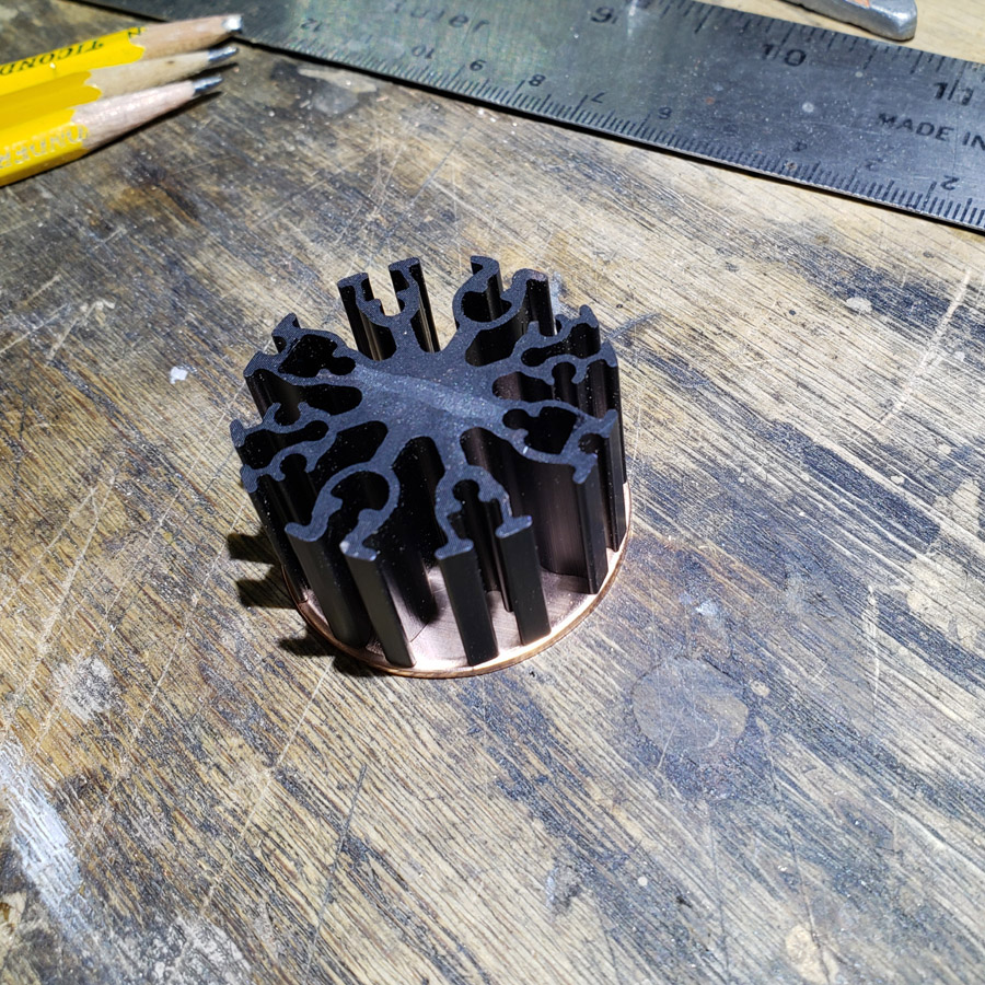
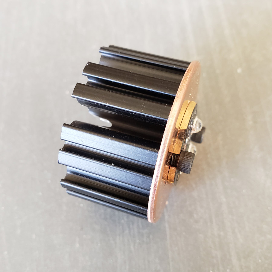
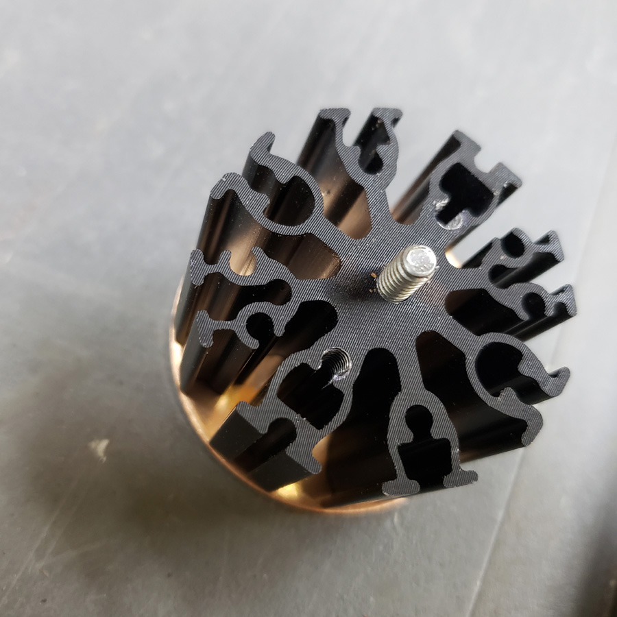
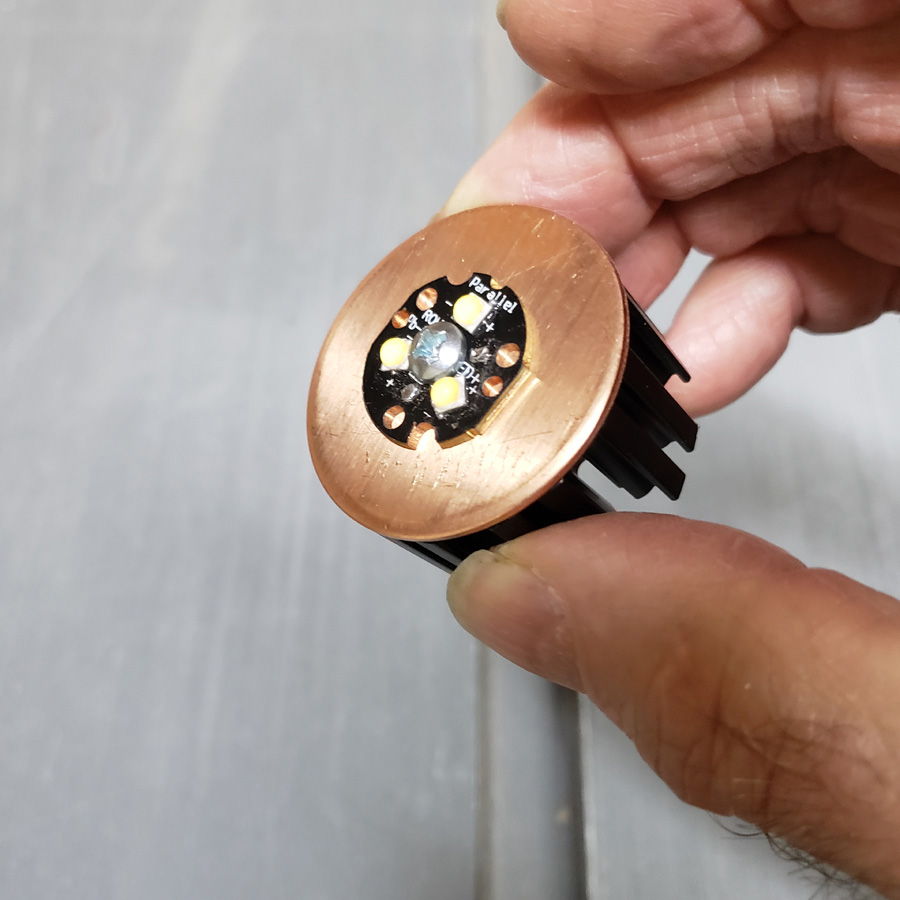
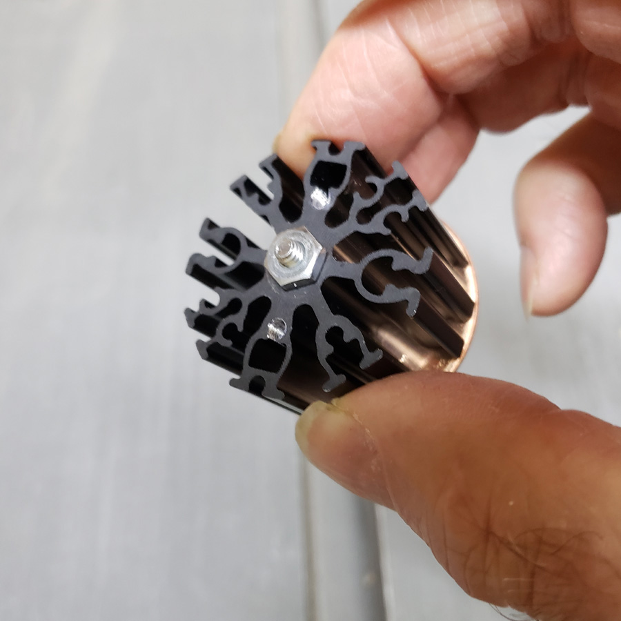
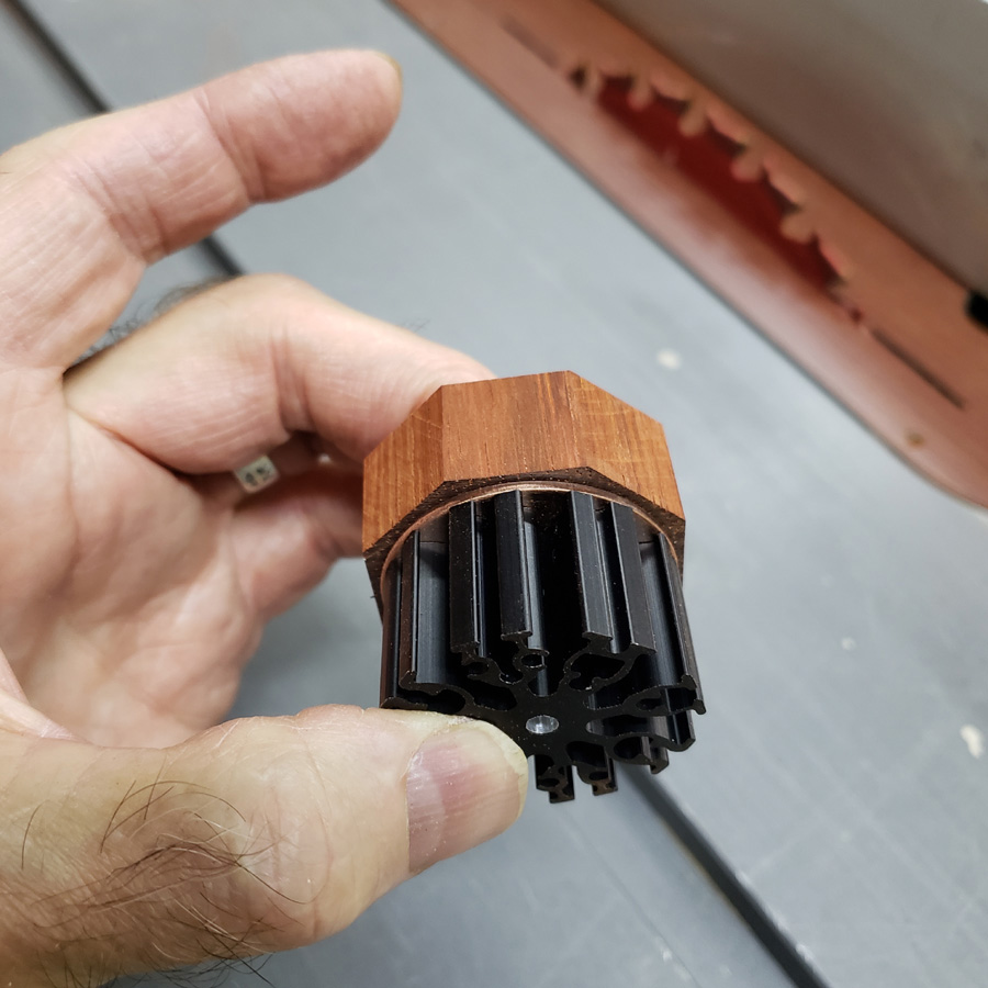
This aluminum heatsink will be incorporated. It is made by Wakefield-Vette. 38mm in diameter, it is 20mm in height.
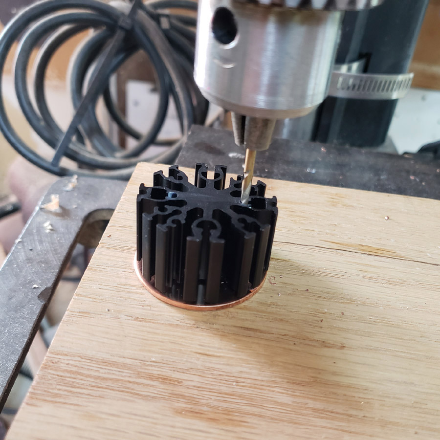
The copper disc was drilled to permit mounting the mcpcb to the copper disc and the copper disc to the heatsink.
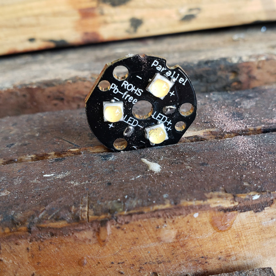
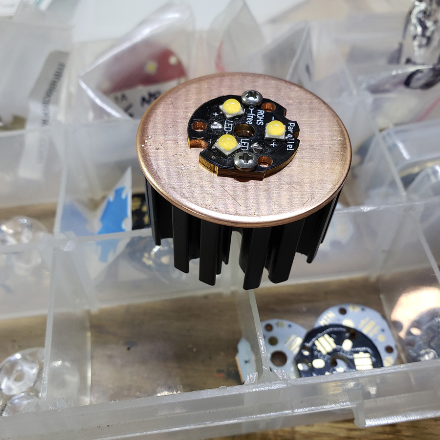
I reflowed the LH351D’s to the mcpcb before I had filed the notches needed to mount the mcpcb to the heatsink. ![]() Fortunately I was able to file the new notches without damaging anything. There are many combinations of mounting holes in the heatsink, but none match up to the mount holes in the KD mcpcb.
Fortunately I was able to file the new notches without damaging anything. There are many combinations of mounting holes in the heatsink, but none match up to the mount holes in the KD mcpcb.
The led’s are 5000K, CRI90; I had them on-hand, left-overs from a previous project purchase. So far, everything I have used for this are left-overs from something else, or parts bought previously and never used due to a change of plans, except for the copper couplers
4-40 screws hold the peices together for a test fit.
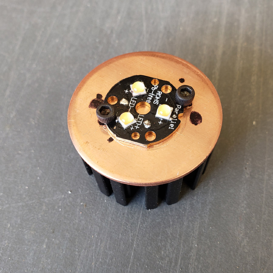
That is a mcpcb from Kaidomain I bought some time ago. I had one of the KD optics that came with the triple red mcpcb I used in last years contest entry. When I bought the KD triple mcpcb’s I was not aware that the optic they use is slightly different from the Carclo ones. Anyhow we’ll use it here.

I did test fire it and it worked fine. The 20mm driver was from Convoy, bought a few years ago and used briefly in some other project before being swapped for a different one.
That may be all the work on this for this week.
Thanks for looking in.
Great work Don ![]() As always
As always ![]()
And now I realized that the idea I was having for an eventual entry is somehow going on the direction of yours, so I will probably refrain from entering (not only because of that though, time, skills and available resources too)! ![]()
Keep it up ![]()
![]()
Looking good Don.
![]()
You got us on the hook again Don ![]()
Great photography too, ![]() Are you using incandescent lights for pictures ? I tried led lighting and it comes out unusable.
Are you using incandescent lights for pictures ? I tried led lighting and it comes out unusable.
.
I just purchased a Cannon camera and still playing / learning to use it.
.
The lighting is mostly the LED workshop ceiling lighting. They are 5000K strips (50 cm long, 12 VDC run off of a few 12 VDC power supplies fed by the 120 VAC house power.) I bought from some seller on Aliexpress a few year ago. Some of the pictures were done with illumination from a cheap zoomie. That has a 5000 K LH351D I swapped in. The photos have all been taken the lazy way; using the camera in my Galaxy 9+. I’ve been using it for most photography for the past 2 years, except for landscape photos when the camera is simply not at its best. Then I use my venerable Nikon D200 or my Panasonic ZS100.
This project will end up looking more like a standard flashlight than any other contest entry I have done, but with some different touches. ![]()
Looking great, Don!
I have made some progress.
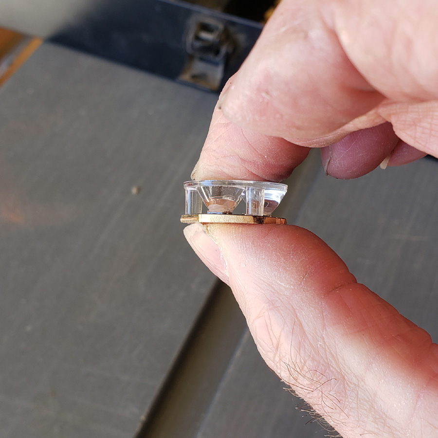
First though, I noticed a couple of problems. The optic legs stick through the mcpcb, so the optic did not seat fully. I thought this was a problem so I sanded the legs shorter so nothing protruded. I am currently not sure if I did the right thing. I has not used a KD triple mcpcb with one of their optics before.
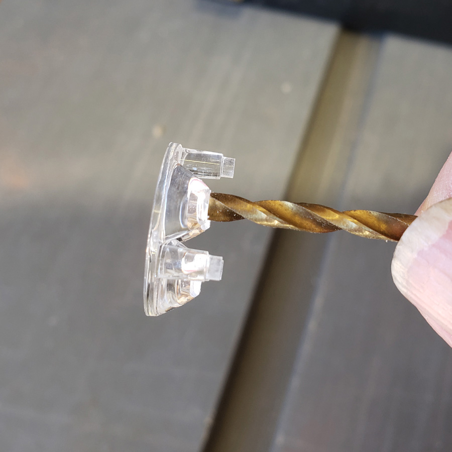
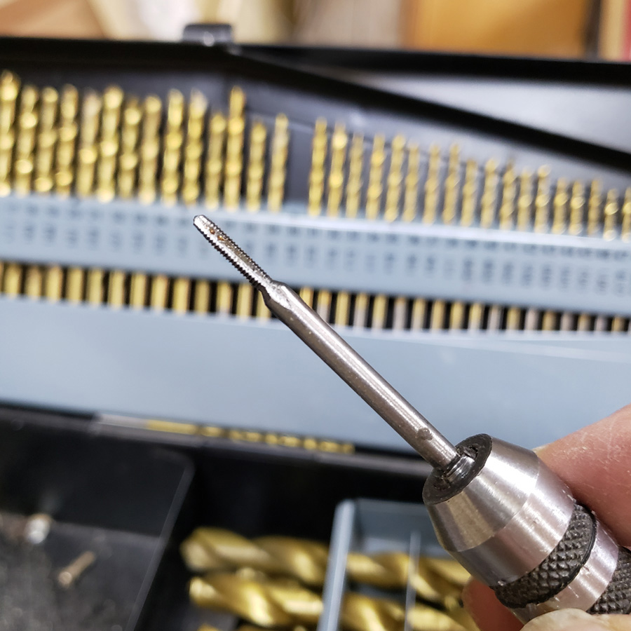
The next issue was that the optic would still not seat fully. Close inspection revealed the portion of the optic that fits over the emmitter did not go as low as it would if the optic was used over a Cree XP-E triple. This project is using the LH351D Samsung. I pondered wheyher or not to slice the domes or to modify the optic, reaming out the “socket” a little. I elected to mod the optic. I used two different sizes of number bits and carefully turned them just using my fingers. I removed just enough material to allow the optic to seat fwith the three legs down against the mcpcb. I also considered drilling clearance holes in the copper disc.
I have not yet wired up the led to check the beam. Hopefully I did not ruin it.
So that was one issue. The other thing I oticed was that I had a slight concentricity problem between the mcpcb and the heat sink as well as with the copper disc that is mounted between the mcpcb and heatsink. The runout was not great but was enough to create possible problems with the next step.
I has a spare copper disc and a spare heatsink though. So I decided to redo this portion of the head assembly.
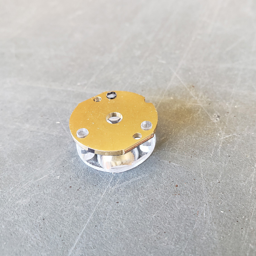
This time I used a different approach. I first found the center of the copper disc. Then drilled a center hole that matched the diamter of the center hole that the factory made in the mcpcb. I used that drilled disc to determine the point to drill through the heatsink center. The result was just about as perfect as could be when using the tools at hand.
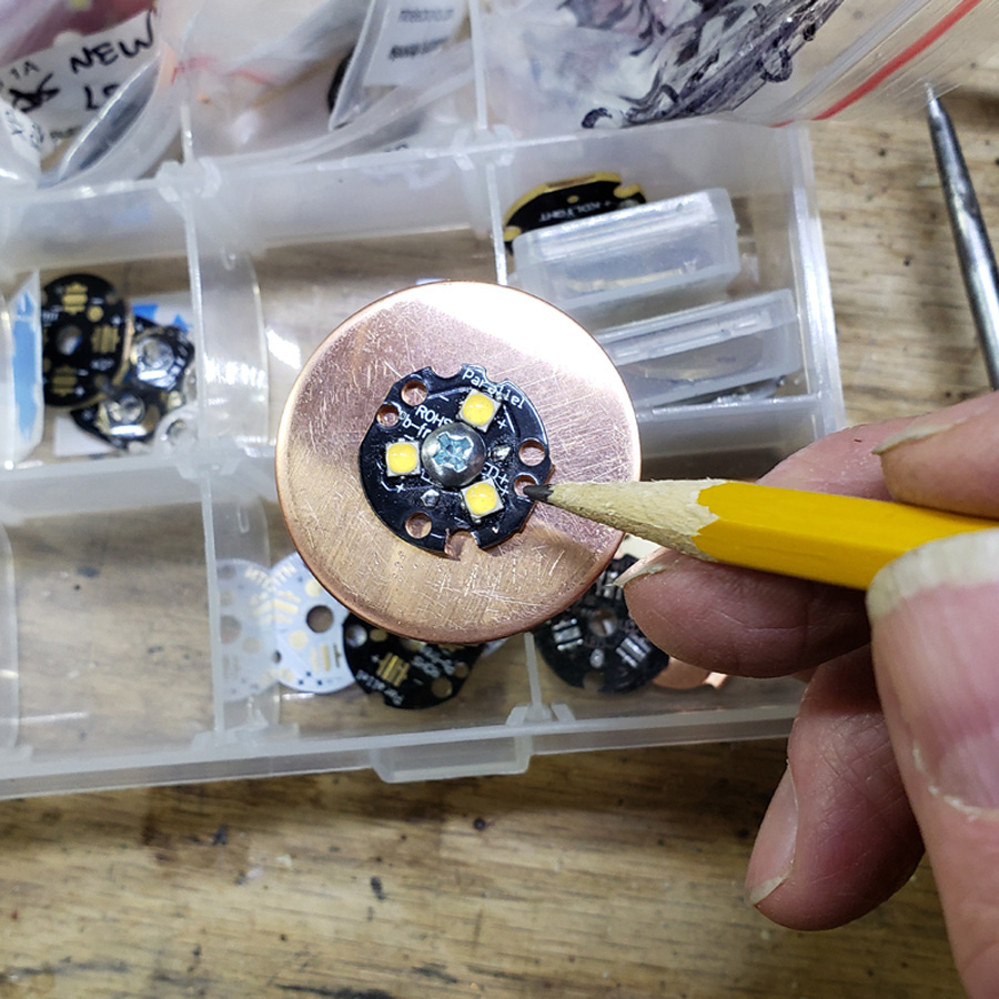
The next issue to correct ws my chosen method of fastening the mcpcb to the copper disc. The previous method relied on using a pait of factory holes in the extrusion that were close to, but not perfectly matched to the notches in the mxpcb. Instead of doing that all over I decided to use the two smaller holes in the mcpcb. The pencil point in the next image indicates the hole pair I mean.
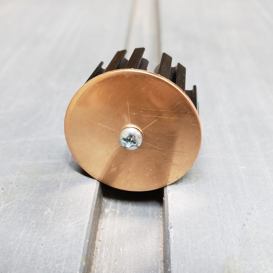
I used a machine screw to secure the mcpcb to the copper disc and heatsink.
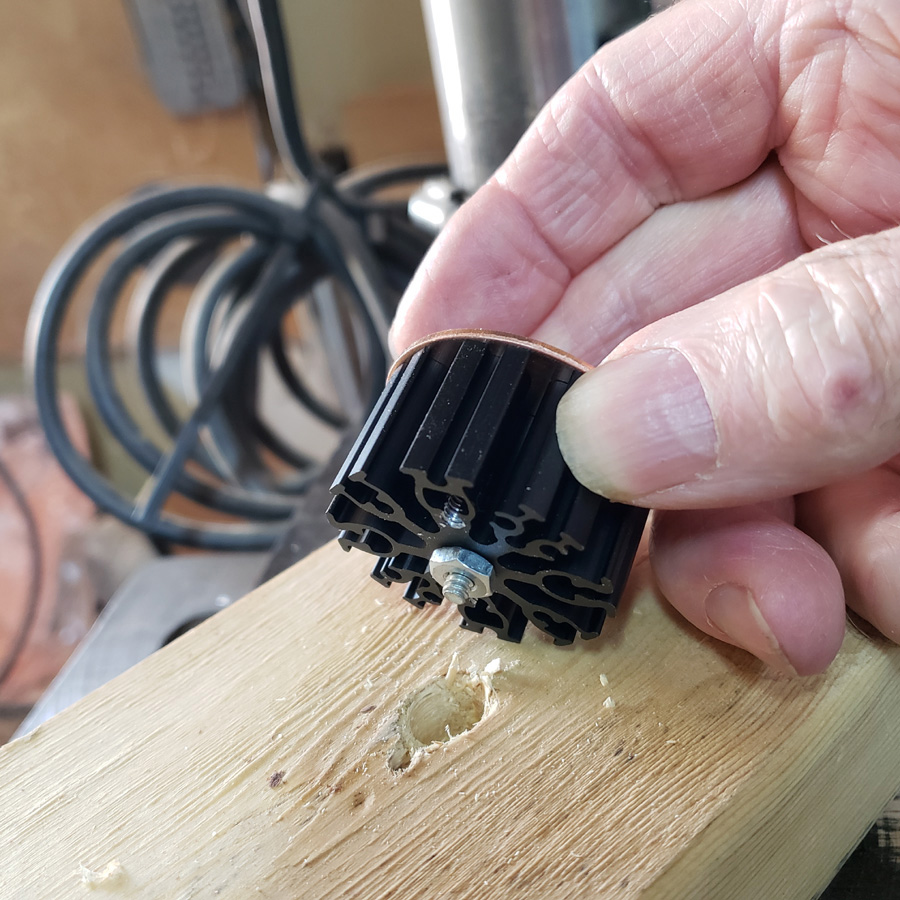
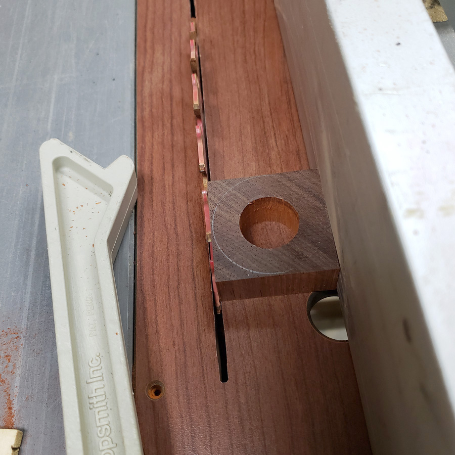
I then drilled a clearance hole in the support wood block and proceeded to drill a dimple in the copper plate, using the holes in the mcpcb as a template.
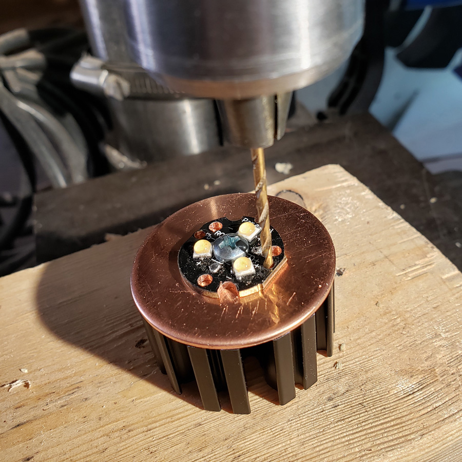
I just barely marked the copper using the drill press. Then disassembled the three pieces and drilled a #50 hole through the copper for the 2 mounting screws.
The holes were hand tapped with a 2-56 thread.
The mcpcb is secured with two 2-56 pan head machine screws.
The heat sink does not have sufficient solid metal in the central area to tap into the aluminum body of the heat sink. The two screws penetrate the copper disc and protrude into a pair of the extruded voids.
Now I am happier with the mcpcb, copper disc and heatsink assembly and am ready for the next section. That’s coming up in the next post.
This next section is a test. It indicates the dirrection this part of the light project is taking, or at least what I am thinking.
I cut a small piece of padauk of a scrap and drilled a 20mm hole in it using a metric forstner bit that arrived from an aliexpress seller yesterday. I bought a small set of the metric bits and they shipped from a US warehouse; only took a few days instead of many weeks, maybe 2 months. The 20mm hole is to fit over the optic and the mcpcb on the front end of the light.
I then used the table saw to trim it down close to the outline of the copper disc making a square shape.
So there is a square. I want an octogon. I elected to sand the corners down to make an octogon, using the disc sander and miter gauge.
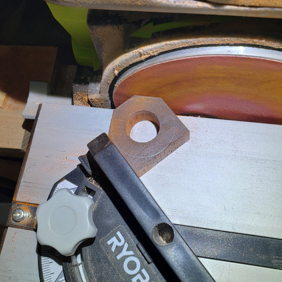
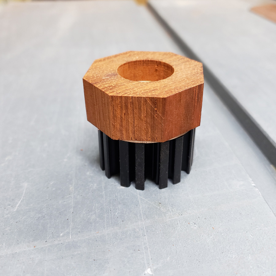
There. Looks like a big wood nut.’
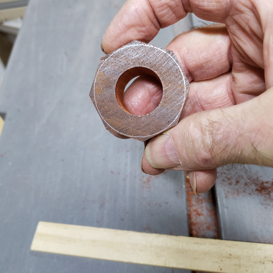
Here is the “nut” fitted over the mcpcb and optic. The optic is a snug fit which is great.
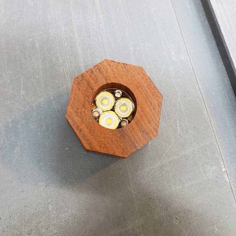
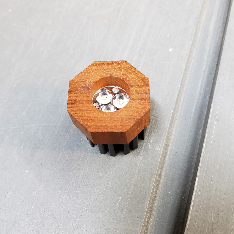
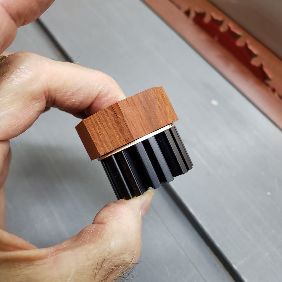
So far, so good. It appears to be feasible.
That is about it for now. Thanks for looking in.
Looking good Don!
Ooops. I almost forgot I had another short set of images for another test piece.
All flashlights need a body. I am wanting to make the body from some bloodwood I have on hand. Bloodwood is very dense; a sp. gr. of 0.95 with average moisture content. It almost won’t float. It can be difficult to work. I’ll see how it goes. I have only 3/4” thick stock so will glue up two small pieces.
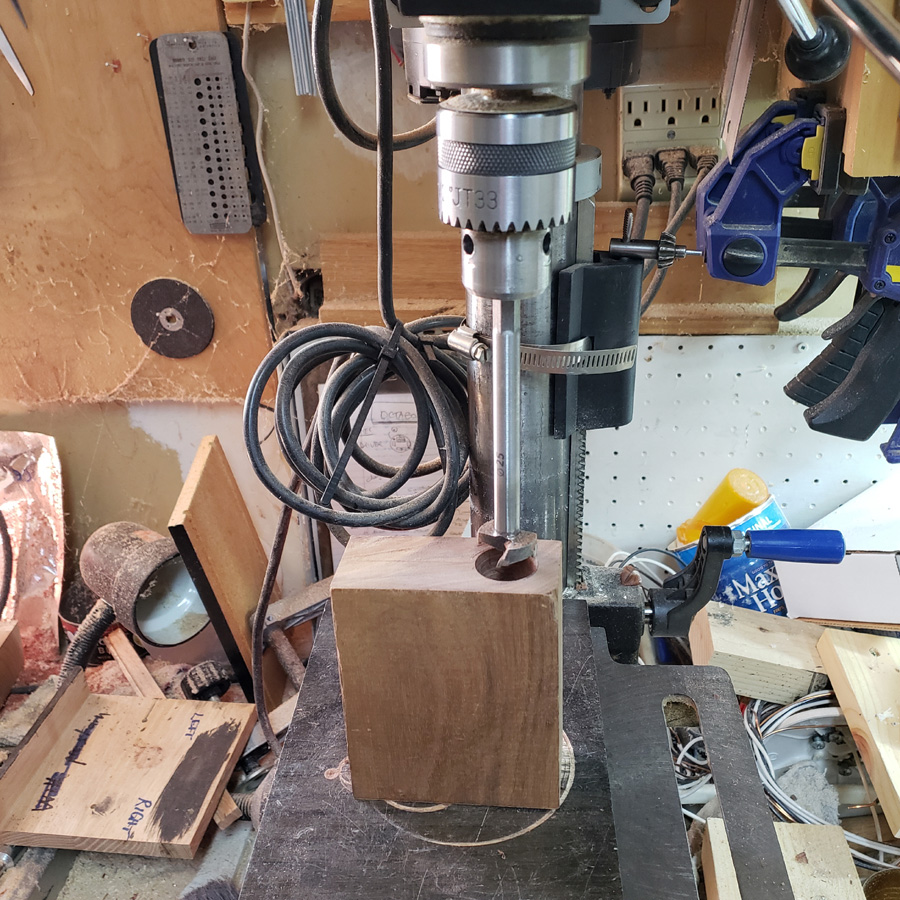
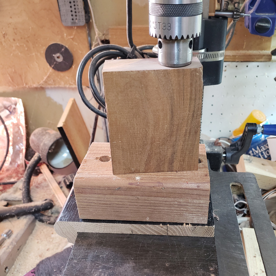
While that glue dries up I thought I’d use a piece of walnut to make a body test. It is 1.5” thick. I marked the centerline with the marking gauge; onec from each side and use the spot in the middle of the two lines as center.
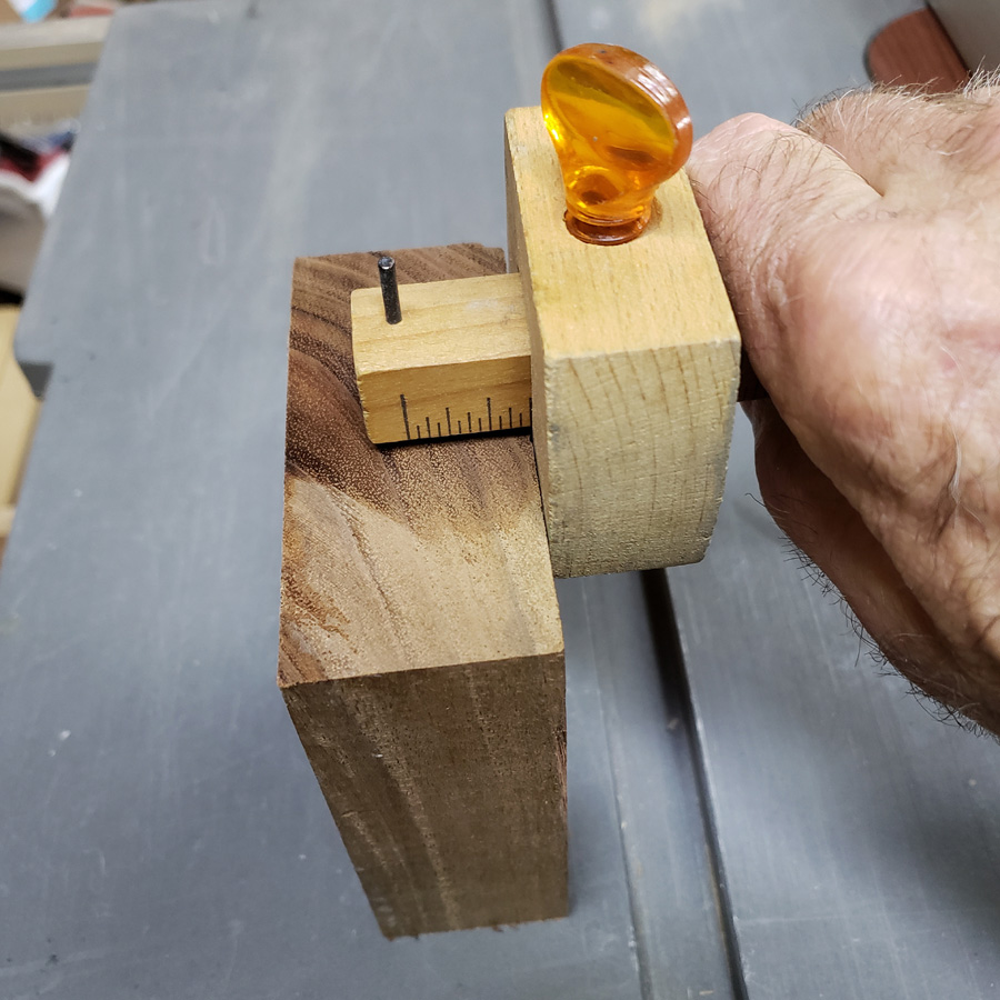
That is a 25mm forstner bit. The shank is just long enough to drill the length I want.
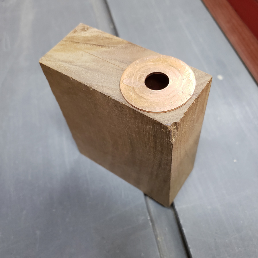
Okay, remember the second rendition of the driver holder/pill that I made, and the slip over sleeve? The O.D. of the sleeve is 24.3mm, a nice slip fit into the 25mm hole that was just bored.

The walnut block is still in the rough state. It will be cut down, but that is all for tonight. Toorrow the bloodwood block will be ready to try drilling. If that goes well the walnut will remain as the test piece and I’ll see how the bloodwood works.
Nice work Don. I see your nearly finished. ![]()
I’m very curious to see how does the optic work. You took the riskier path.
Very nice work and photography too, I really like your hand made tools. ![]()
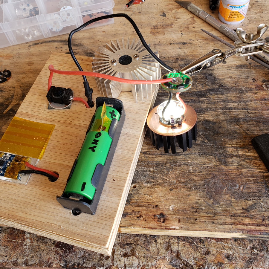
I don’t have a room without a window, even the shop has windows, so a good test will have to wait until night. However, I was curious about the potic myself so did the best I could. I made a temporary hookup between mcpcb with optic on the heatsink—- wires to the driver —- wires to a cell holder and some alligator clips. Most of the closets are too full of whatever to allow a person inside but one small coat closet had just enough space. Not enough space for a beamshot. The near white wall was only 30 inches from the mcpcb/optic. But there are no strange artifacts showing, no strange colors or unusual shadows or hotspots, so I think the optic still works satisfactorily.
I made some more progress on some parts today. I took pictures. I’ll post an update later this evening most likely.
.
.
.
I downsized the earlier photos of the parts I re-did if anyone looks back.
What I did today on this project.
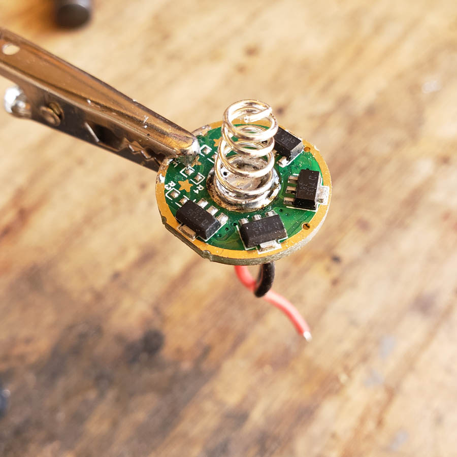
I soldered a spring to the driver board. There used to be one on there at one time but I removed it for some reason
I needed to make a bayonet mount “thingy”. I found a brass tube with a closed end in the junk box and cut off a short piece. Cleaned the side of the copper tube-pill I made earlier, applied flux. some heat and silver solder. I forgot to take a picture until I had begun cleaning up the flux and excess solder.
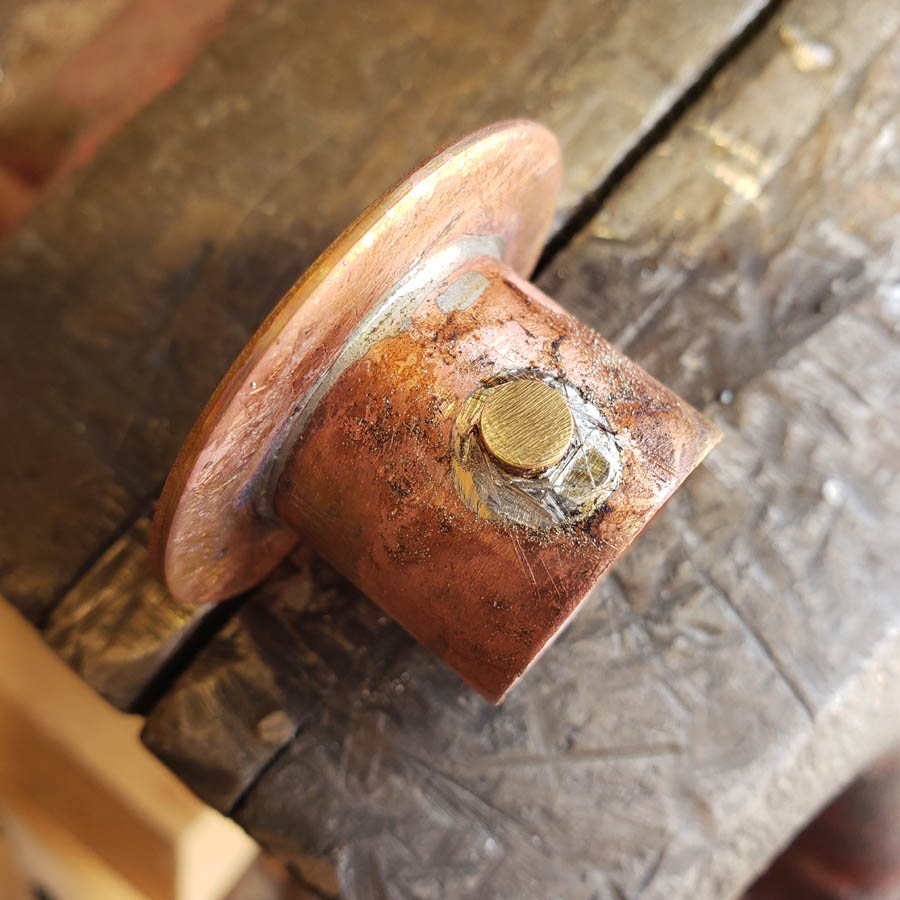
It cleaned up pretty good…
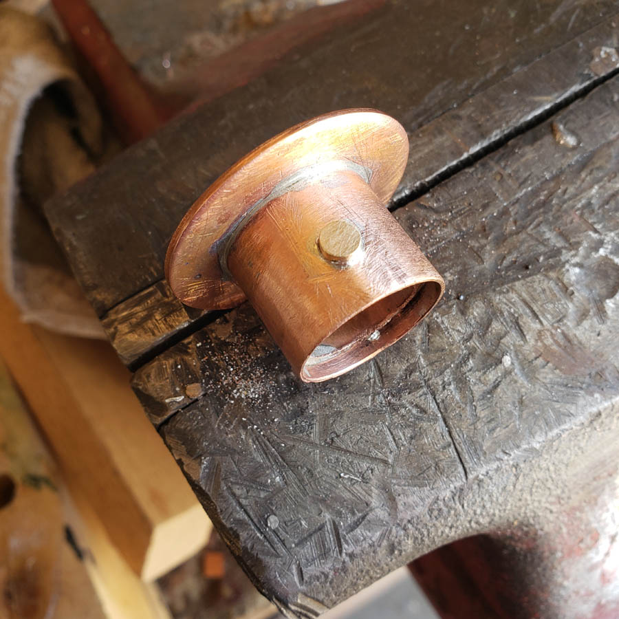
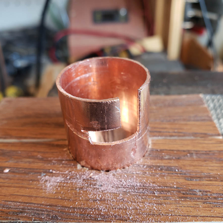
The copper coupler needs a slot cut to clear the brass bump.
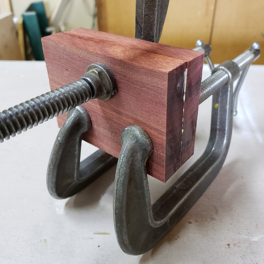
I used one of my wood tube clamps to hold the piece wirhout crushing the shape. I used a hacksaw blade to make the first cuts, then files…
Small file…
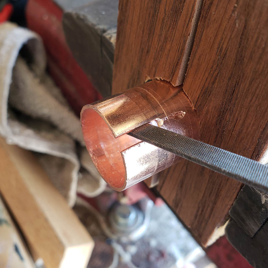
Then when the slot was larger I switched to a bigger file
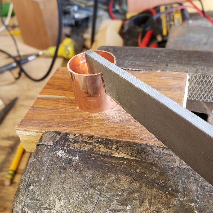
It works…
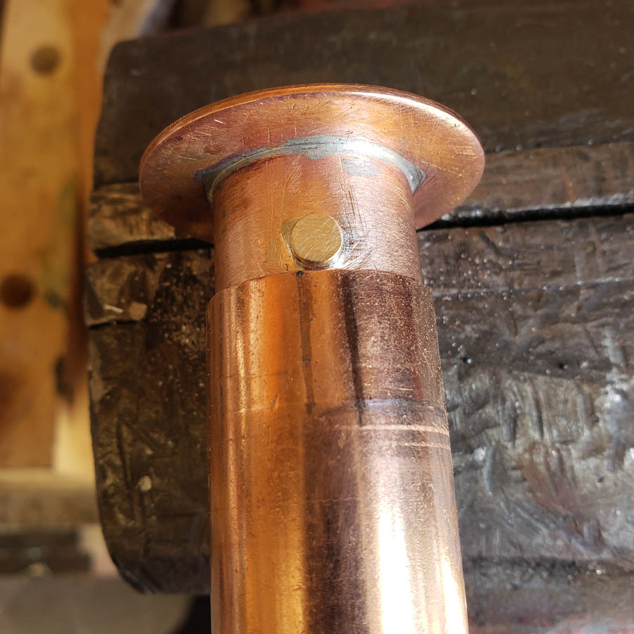
The hard to see pencil mark indicates where the slot needs to go next. The slot will be cut “down” not up where the more visible pencil marks are. Those are depth guide marks, niot for the slot. …
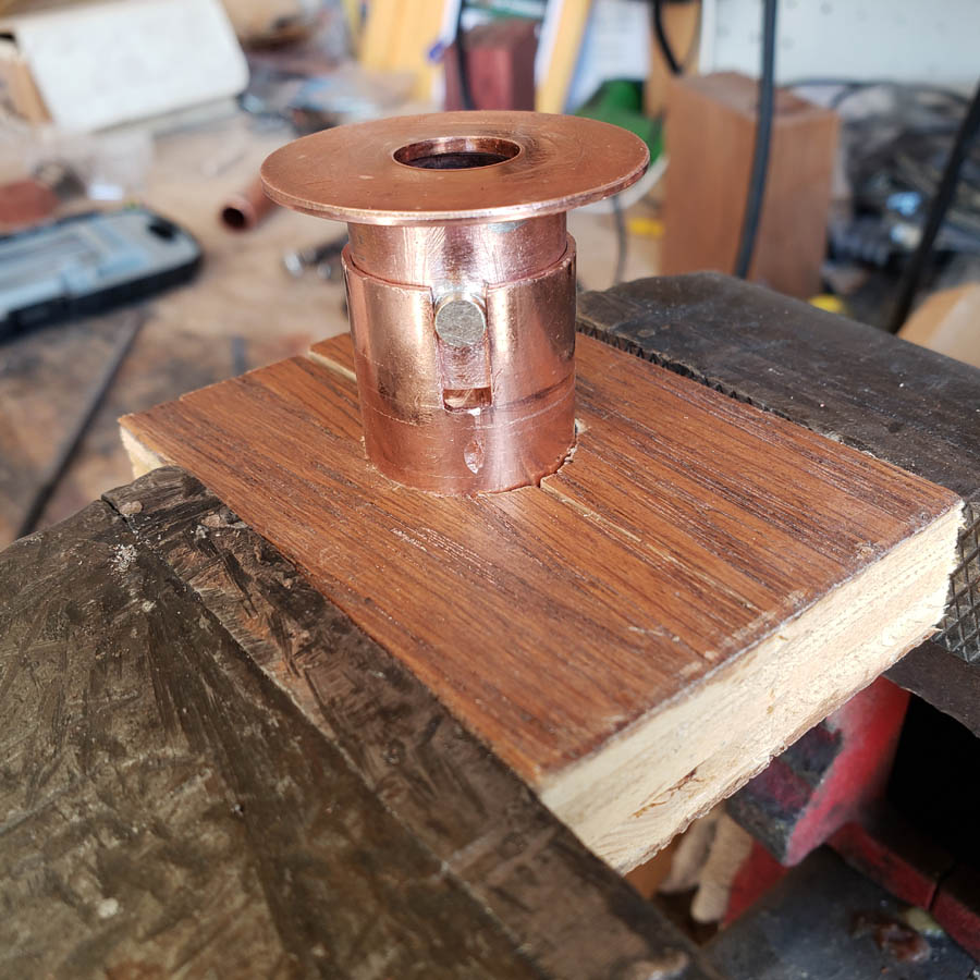
Rough, but getting there…
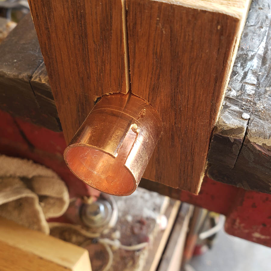
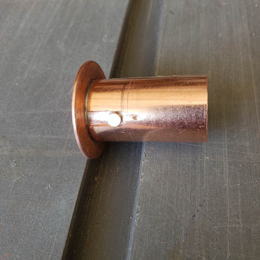
The completed bayonet locking mount…
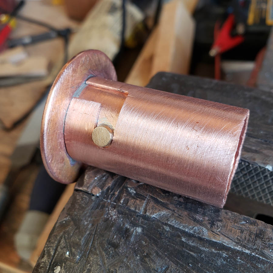
As I filed off the protruding portion of the brass the solid part was removed and the hollow revealed. It does not look as nice but the solder puddled in the hollow indicates I did make a good silver solder joint as the solder was drawn in.
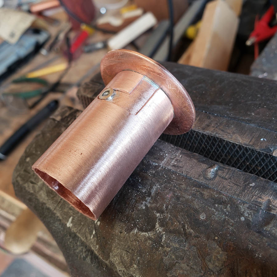
That is all for now. The washer end of this piece with be mounted to the rear end of the finned heatsink. The mcpcb with its washer is to be mounted on the front end of the heatsink.
More coming later, maybe tomorrow.
Glad to hear your optic mod worked out. Looking forward to how it all turns out!