Wow that looks amazing. Love the mock-up photo.
Nice work!! ![]()
Cool design.
Orsm work Don. Its hard to get anything looking nicer than natures own work fettled by a craftsman. ![]()
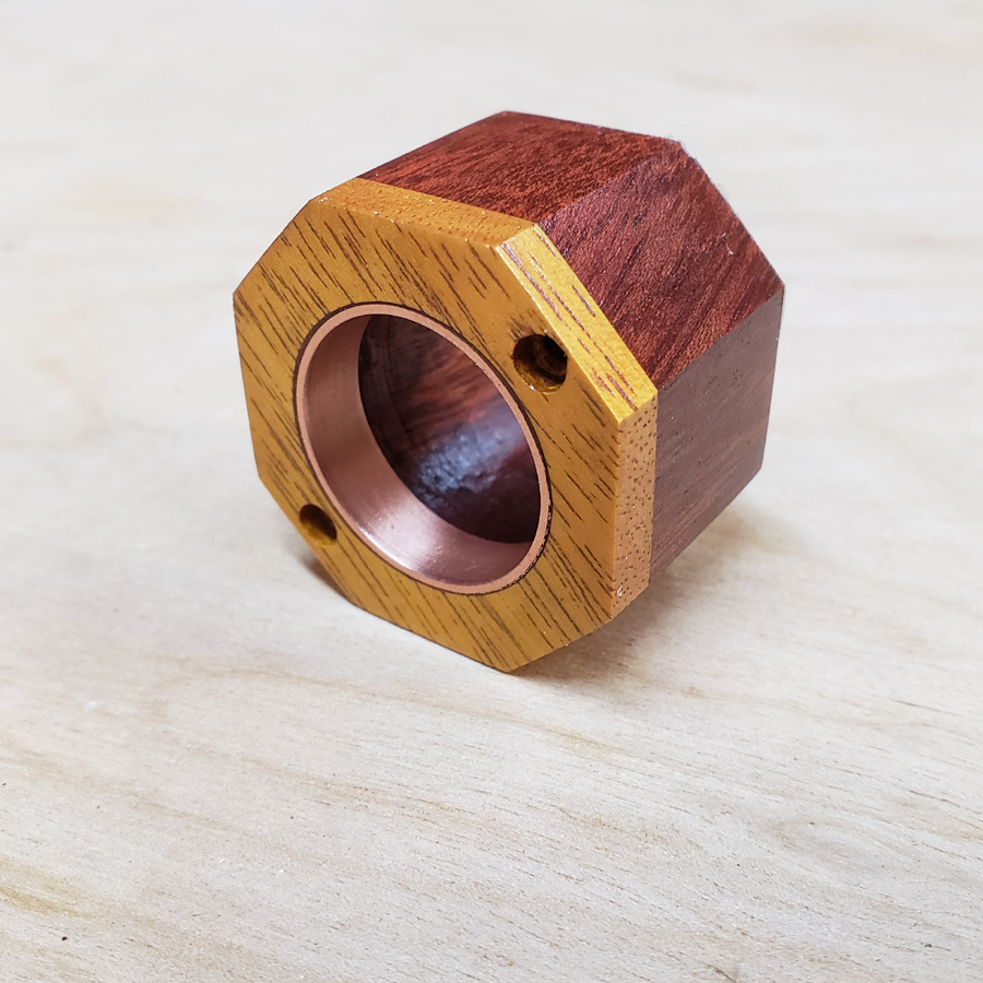
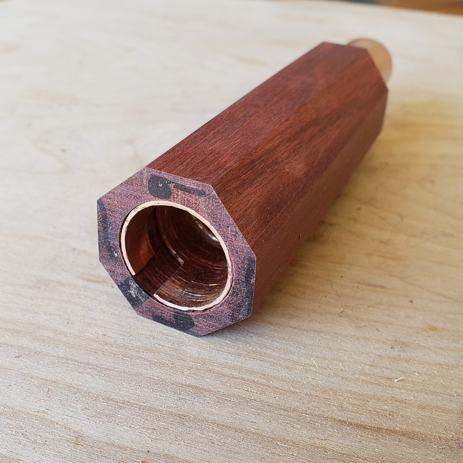
After the epoxy set hard this is what I had…
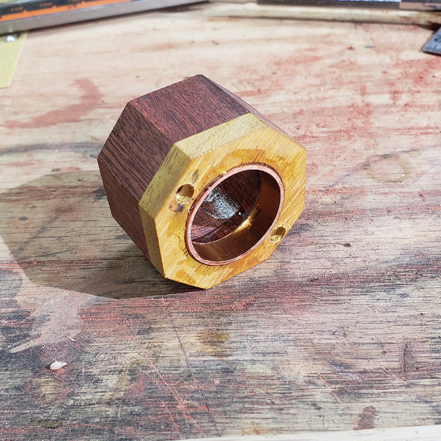
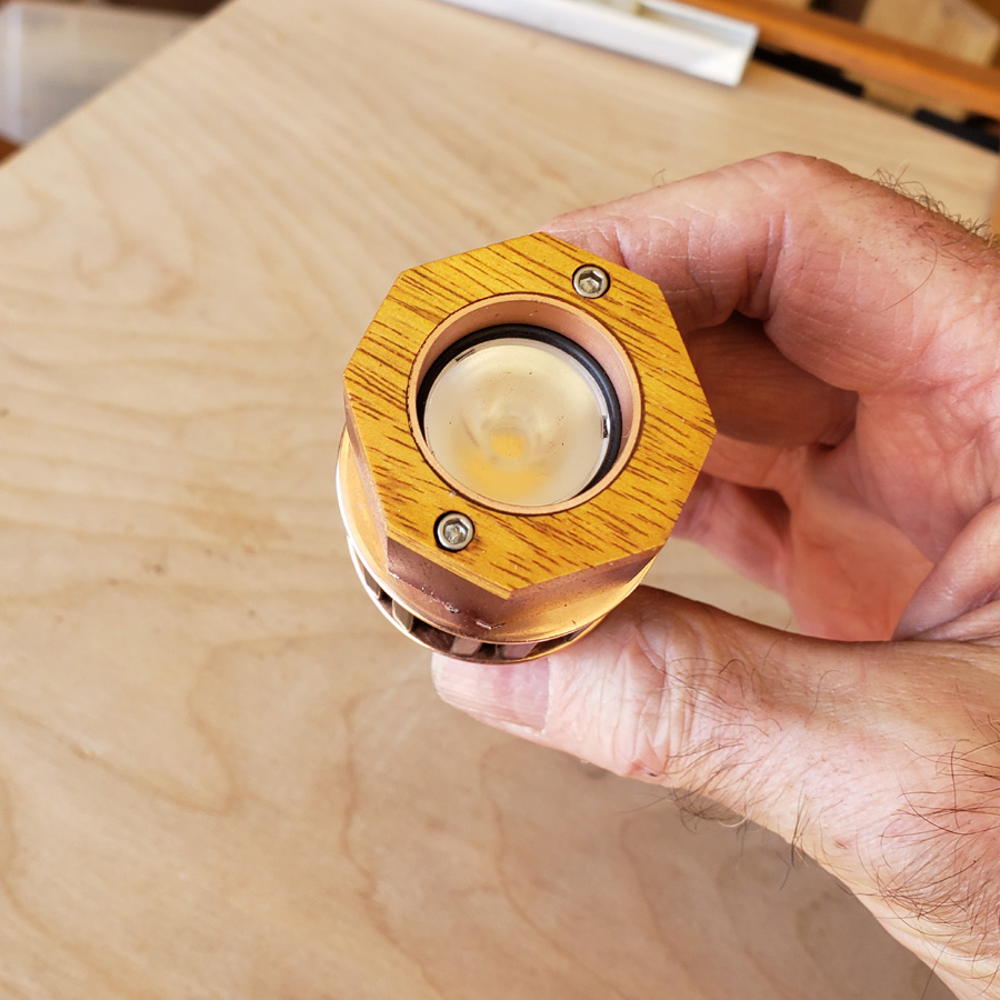
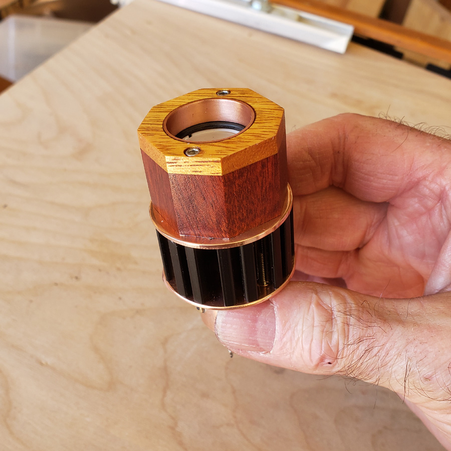
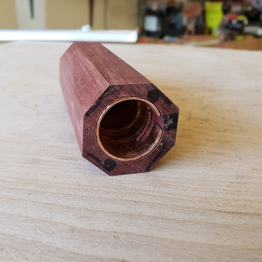
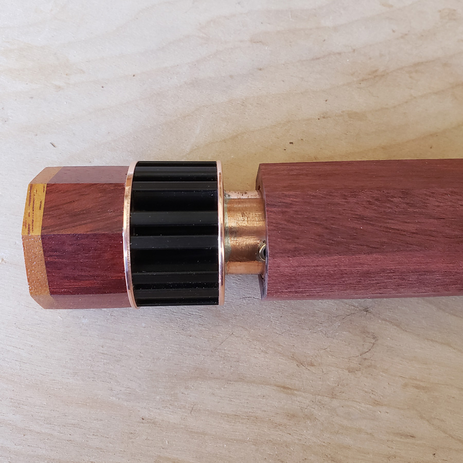
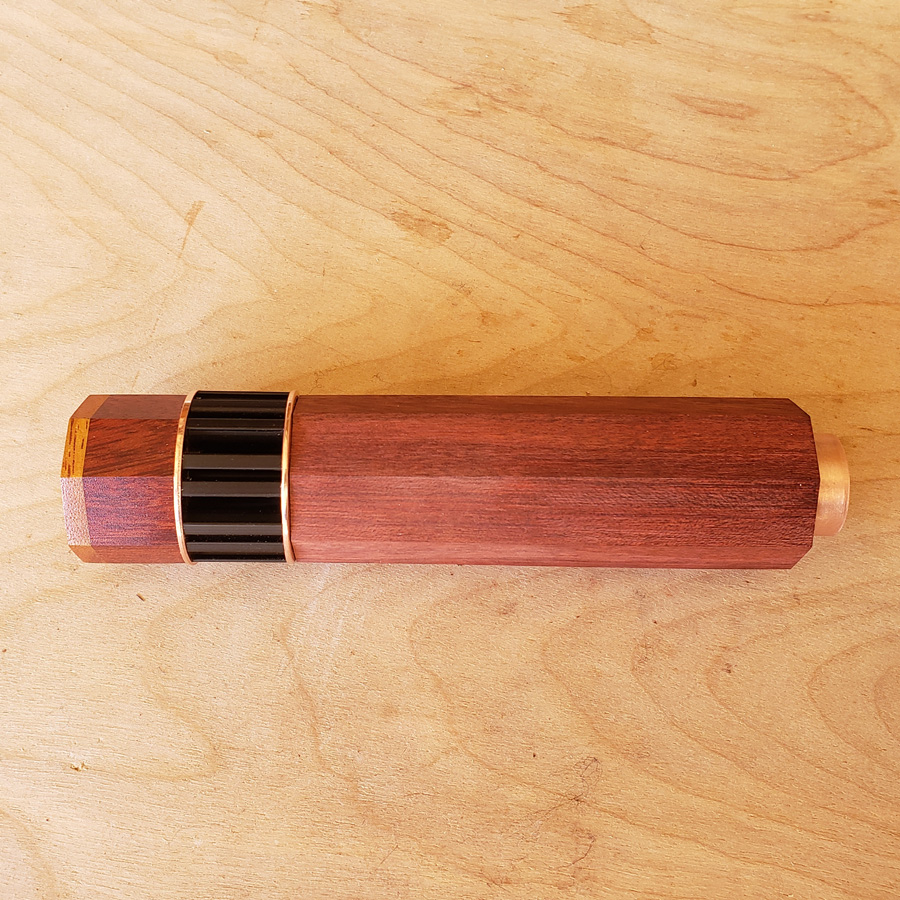
After sanding the front with the benchtop beltsander with 180 grit I sanded the front face and the 8 octagon faces manually working my way through 220, 320, 400, 600 and 800 grit sandpapers. I sanded the copper ring insert with same grits, sandpaper wrapped on a finger. Then I sprayed the head with clear satin finish lacquer.
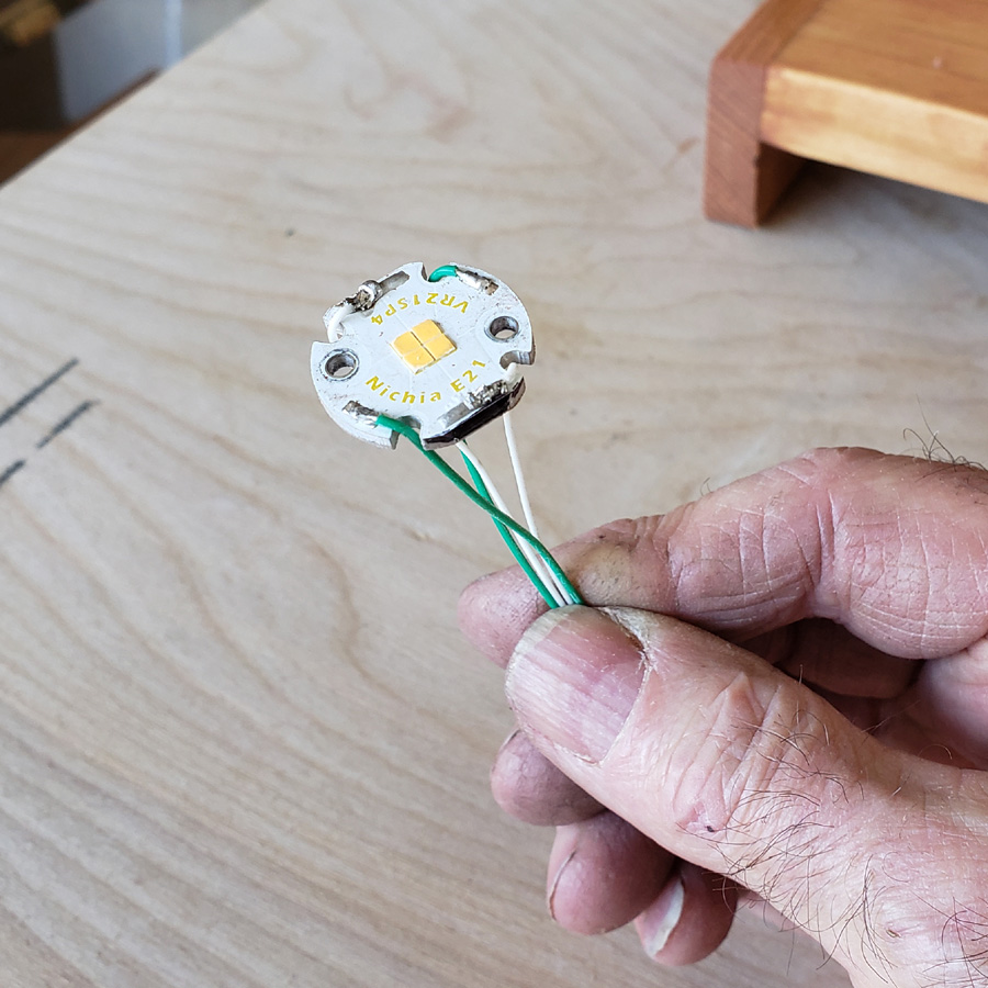
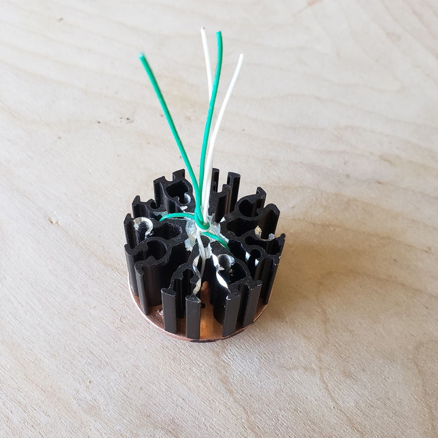
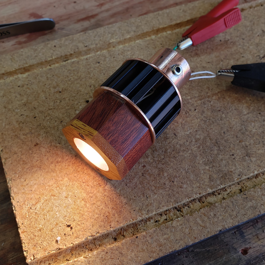
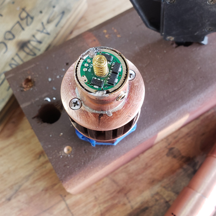
On to the mcpcb with Nichia E21A emitter, from virence.com. This mcpcb uses 4 wires to connect all four emitters to a power source/driver when all 4 emitters are used in parallel. Normally I would use some silicone insulated wires, probably 24 gauge for a light like this. However the wires have to take a course with lots of turns following channels in the heatsink. I was worried about nicking the insulation as well as the OD of the silicone wires. So I decided to use 26 gauge teflon insulated wires. They are much thinner and the insulation is very tough. It is also stiffer which is a compromise.
IF I had used the triple as I started out this wiring would have been sipler at the wires could then have a direct run down the center hole in the mcpcb and heatsink. OH well.
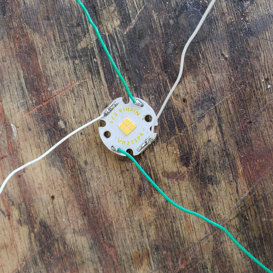
Green is red (+) and white is black (-).
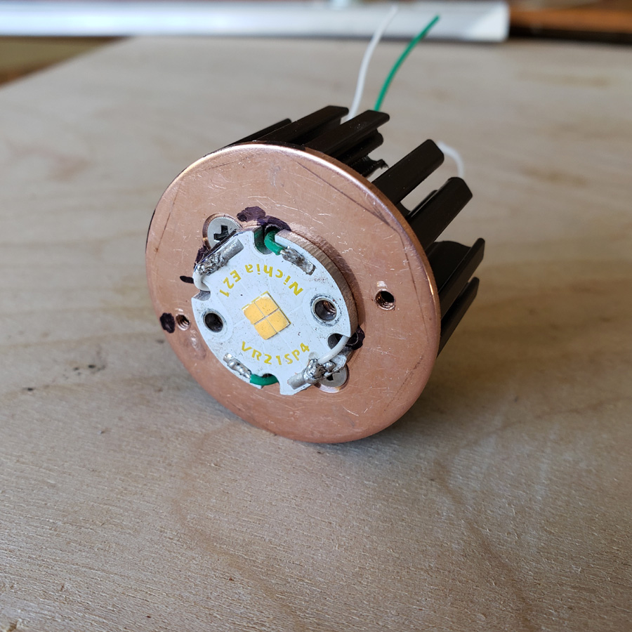
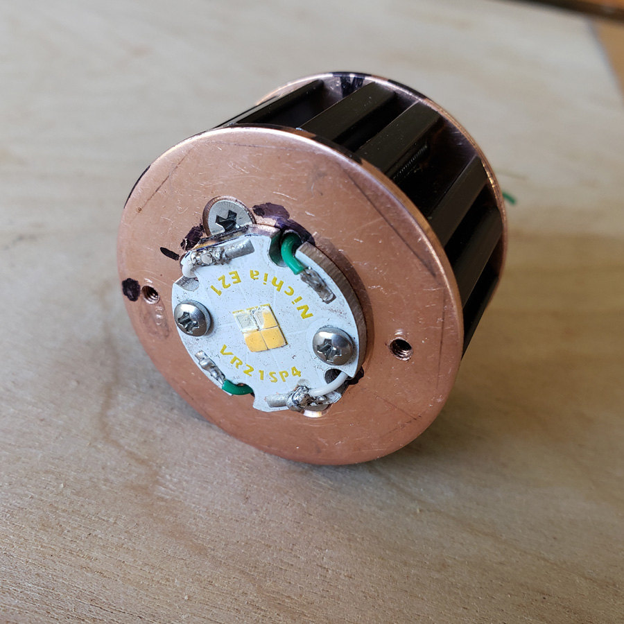
Here is the mcpcb fitted to the copper disc and that fastened to the heatsink. Each of the four wires has its own route through the mcpcb and heatsink.
Twisted together the wires then will pass through the rear copper disc and into the copper driver mount/pill.
A moment of inattention brings disaster and a swear word or too!!! ![]()
![]()
It is a good thing I got two of these mcpcb’s when I ordered from clemence. ![]()
![]() I transferred the wires to the second mcpcb.
I transferred the wires to the second mcpcb.
With the front end of the head assembled I connected the mcpcb to my benchtop power supply. Here it is at 2.2 or was it 2.3 volts and .20 amp.
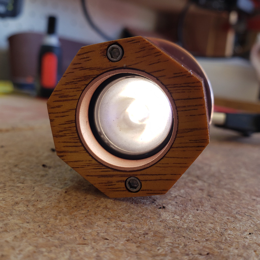
Here it is with a little more voltage and amps…. 2.5 and .40 amps
That’s it for now. Thanks for looking.
![]()
![]()
![]()
Gee, it’s always something. ![]() I soldered the driver to the led wires and nothing happened when I connected power to the driver.
I soldered the driver to the led wires and nothing happened when I connected power to the driver. ![]() The 20mm driver worked a month or so ago, but for some reason won’t light up any led/mcpcb I connect to it today. Different drivers make this mcpcb/led unit light up good. This is the only 20mm driver I have at present. I need some luck figuring this out or possibly need a new driver. Thankfully mtnelectronics has 175 in stock right now.
The 20mm driver worked a month or so ago, but for some reason won’t light up any led/mcpcb I connect to it today. Different drivers make this mcpcb/led unit light up good. This is the only 20mm driver I have at present. I need some luck figuring this out or possibly need a new driver. Thankfully mtnelectronics has 175 in stock right now.
And then the belt on the bench sander flew apart, broke at the seam, when I applied the cleaning stick. I need to order some more as I found that was my last of that grit.
Maybe something is trying to tell me to get back to the small table I’m supposed to be making.
Oh i feel your pain. Invisible magic smoke , tool maintenance. The problem is when a build goes to plan just once, we expect it all the time ![]()
This is a great build thread, i look forward to each new development. It’s pure joy to see how you setup the tools and crafted the pieces to bring out the beauty of the wood.
Bugger. ![]()
That was more or less my reaction, too.
I have no idea what went wrong. I ordered another. C’est la vie!
I have moved forward some… sorry, but the next image is out of focus. I guess that is what happens when juggling a lit butane torch, and the phone camera. The torch head and flame are just barely visible. The square in the background is sharp though. ![]()
Anyhow, it was time to solder the bayonet sleeve to the main battery carrier tube.
Once it cooled I cleaned it up.
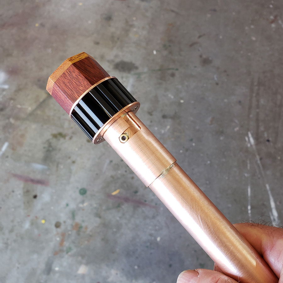
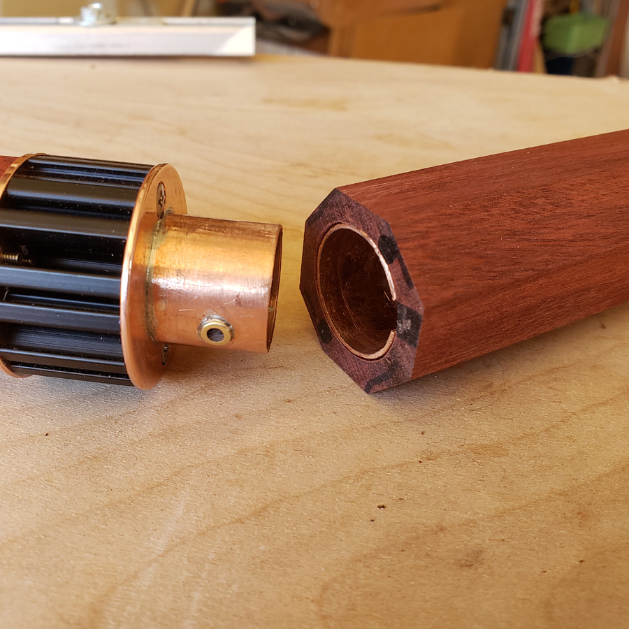
Here’s the head assembly with the bayonet sleeve and body inner tube fitted into place.
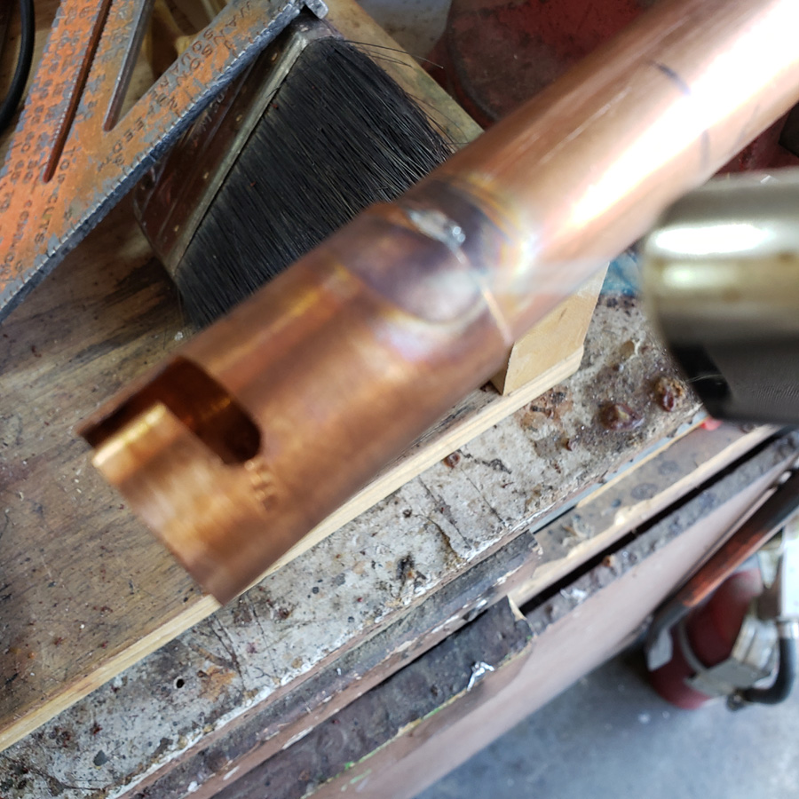
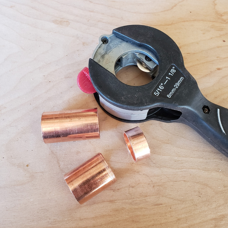
I needed some sleeve/coupler sections and used my tubing cutter to do the cutting. Slow going because the short lengths didn’t provide much grip for turning in the cutter, but more accurate than me trying to hacksaw and maintain a straight end.
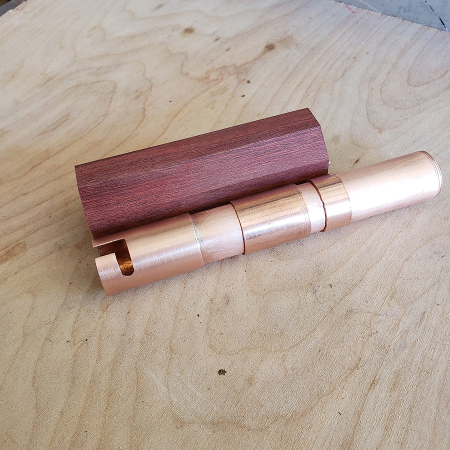
Parts….
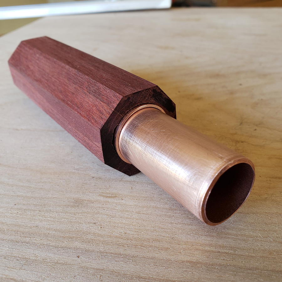
This is the wood body tube with the copper bayonet assembly inserted. The inner copper and outer wood pieces need to be mated; screwed or bolted or glued. I will be fixing them together with a machine screw or two in a later step.
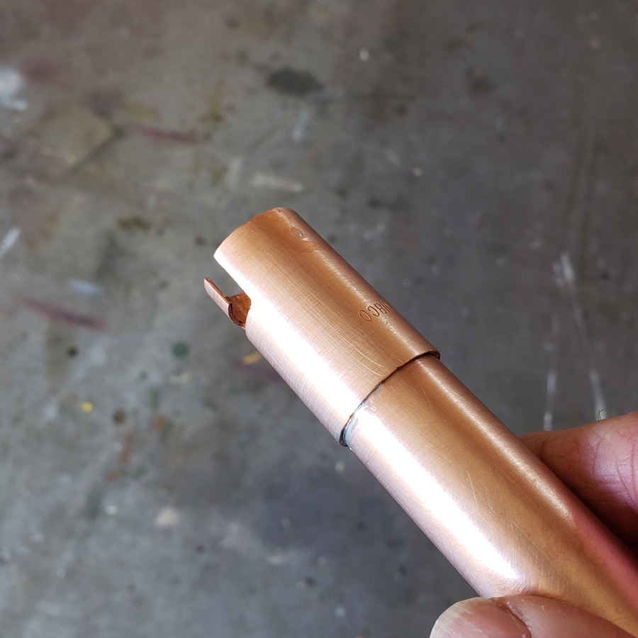
The bayonet slot can be seen….
The tail end. The copper tube still needs to be trimmed to length. I won’t know the exact length until the driver is secured in its holder.
Trial fitting of head and body parts… The black marker square denotes the position of the slot in the copper sleeve.
The new driver arrived. I flashed it with Crescendo and then tested it. It worked. Then it was soldered in place. That was easier said than done. The mass of copper dissipated the applied heat rather quickly. Eventually I was able to get the solder to flow between the copper tube mount and the ground ring on the driver.
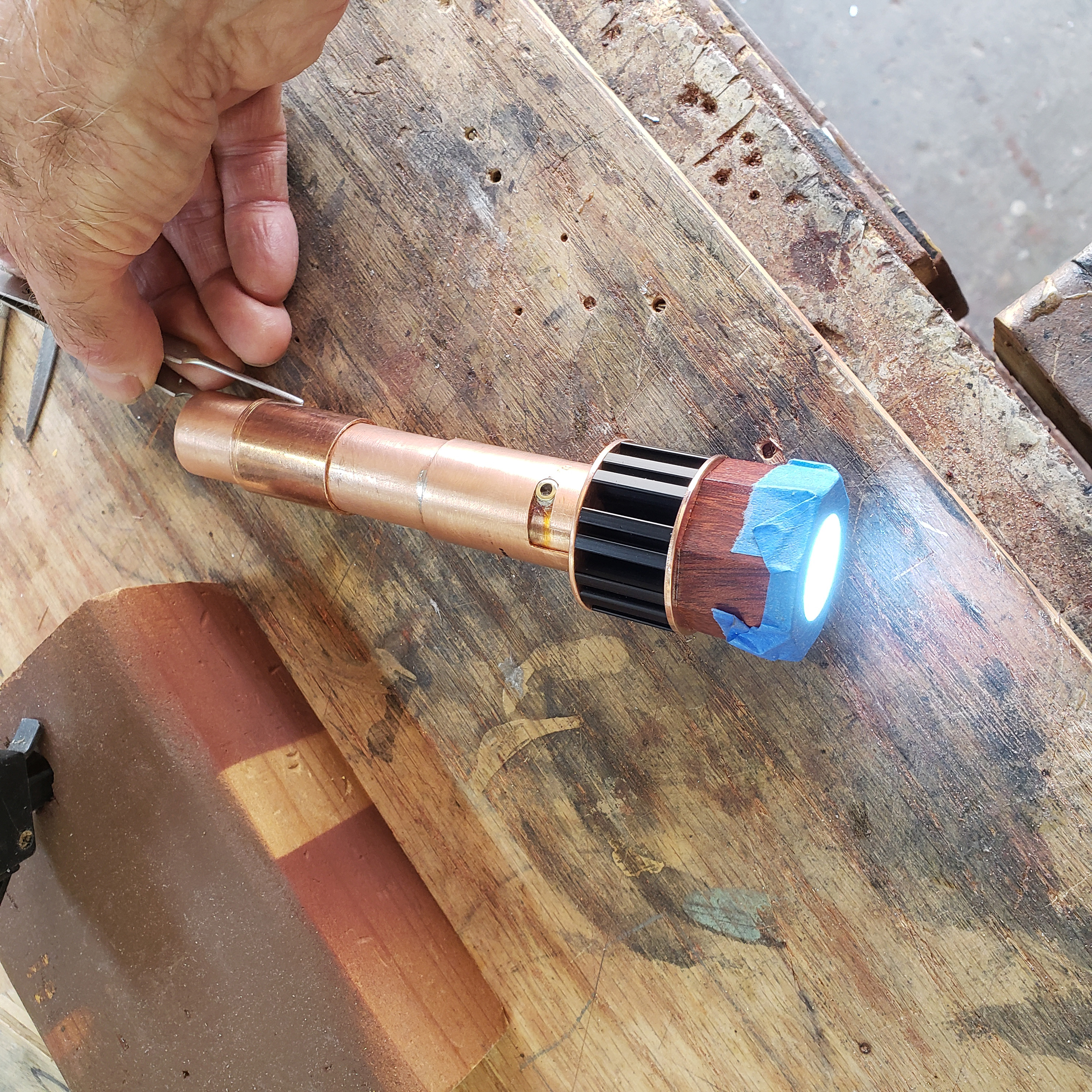
After things cooled down I tested again and was able to confirm that all was good. I had not fried any parts. ![]() The ramping up and down, etc all functioned. The image shows the head and metal body tube assembled. There is an 18650 cell inserted and I used a pair of tweezers to make/break the circuit to check the operation of the driver firmware. The blue masking tape is to protect the clear coated wood portion of the head during handling.
The ramping up and down, etc all functioned. The image shows the head and metal body tube assembled. There is an 18650 cell inserted and I used a pair of tweezers to make/break the circuit to check the operation of the driver firmware. The blue masking tape is to protect the clear coated wood portion of the head during handling.
The next step is to finalize which one of the partially thought through tailcap and switch assemblies to use and build. I have had several ideas and as I ponder through a mental build, usually find difficulties that need to be worked through.
If you haven’t figured it out, because I don’t think I detailed it yet, this light is a traditional tailcap reverse clicky switch switch design.
It is fitting up nicely ![]()
I like your shop too ![]()
On the home stretch now MD. Would a small torch be better heating the copper tube to solder the driver in?
I did use a small butane torch to preheat the assembly, but was afraid I was going to burn insulation on a wire inside the copper tube or inadvertently waver and toast a chip on the board. I seem to remember having done that before. :person_facepalming:
Anyhow that did work out okay in the end.
![]()
I don’t blame you, I’m terrified to use torches like that. I’d probably have heated the smallest disassemble-able portion of it on my hotplate and then soldered. I haven’t done this yet, but it’s my plan for soldering to brass/copper pills etc.
Oh yeah!!!
Nice progress! ![]()
The wood design looks really special, like an expensive custom flashlight. ![]()
This light will have its switch located in the tailend. It will be an Onten 1288 reverse clicky switch. Did you know that Omten makes over a dozen varieties of the 1288 switch. Some are even momentary contact types. Most are reverse clickies and vary in either color (white or black) or vary in the type of connecting contacts on the outside of the switch. There is one particular odel I wanted. I could not find any available in the US, so I have some coming from someplace in Cina.
While I wait for the switch order I still have some parts to make.
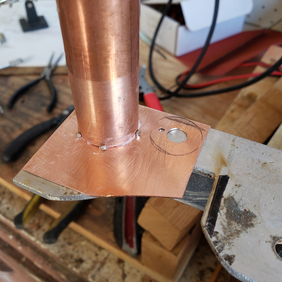
The switch will be mounted in its own module that will slip into the tail. The module will be fitted inside a short piece of 3/4” tubing. The first task with it is to silver silder a flat copper cap to the end of the 3/4” copper tube.
In the following image please ignore the portion with the holes drilled in the copper plate. That is an unused left over from another idea.
The copper pieces have been cleaned and a thin film of silver solder flux applied to the end of the tubing. I cut short little lengths of silver solder and placed them around the circumference of the tubing. When the copper is heated sufficiently with the butane torch the flux will have melted and spread. As soon at the melting point is reached the solder melts and capillary action draws the solder into the space between the tubing end and the plate.
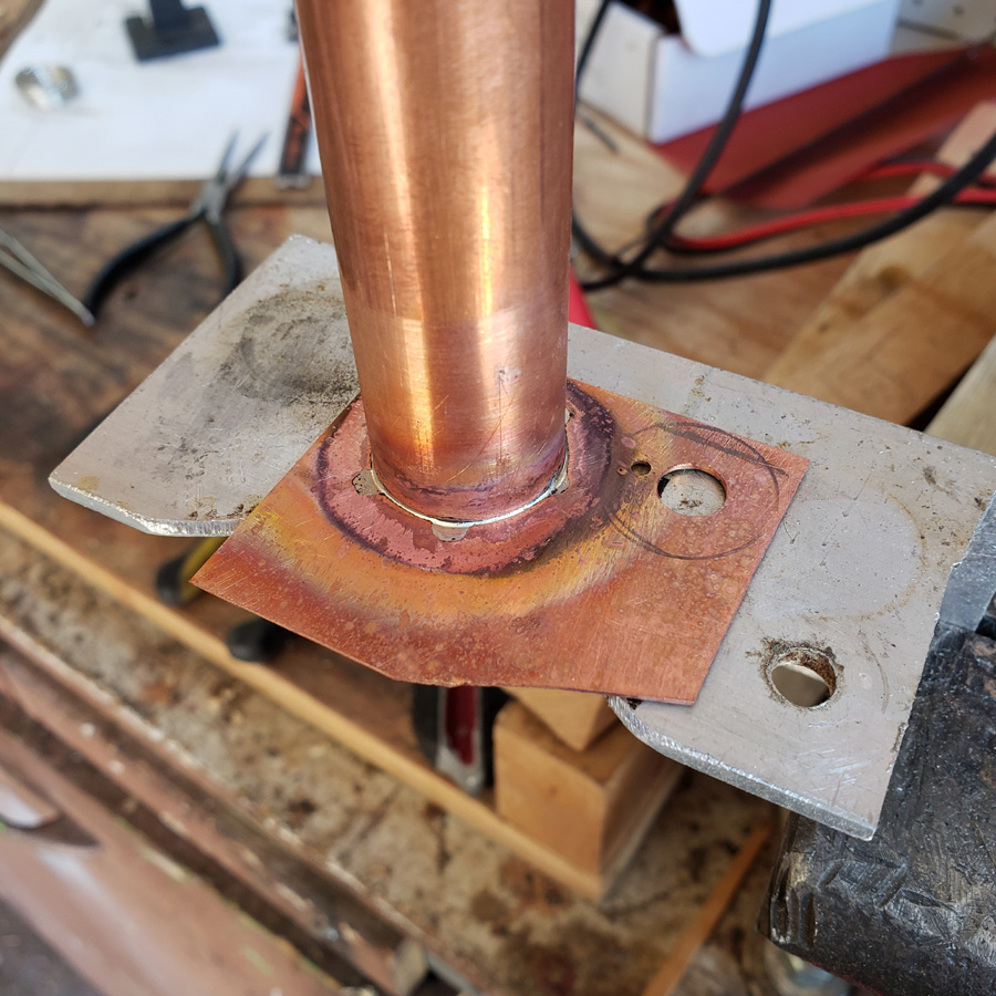
Here it is with the soldering completed. FYI, the piece of aluminum angle has a section cut out that allows the work to be heated directly from underneath with the torch flame.
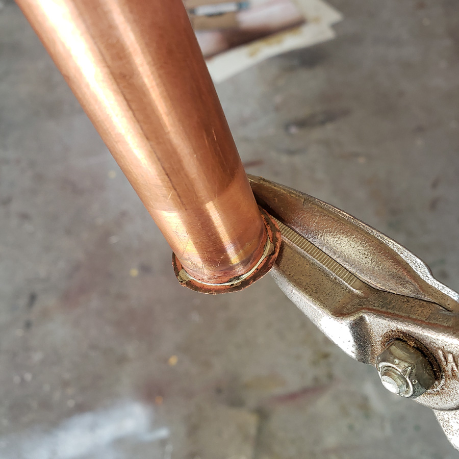
I only need a thin rim of the flat copper around the perimeter. First I used snips to rough out the shape.
Here it is with a short length of scrap tubing slipped over the tube. This piece is cut off of a 3/4” plumbing coupler sleeve. When joining lengths of copper pipe for plumbing these sleeves bridge the joint and are soldered in place. For this pipe size the coupler sleeves are about 1-5/8” long. Special purpose longer ones are available.
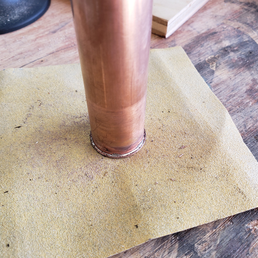
The flat cap piece was sanded or ground down using a belt sander. The piece of coupler acts as a stop when the piece is held on the top of the moving sander belt and rotated by hand as the sander runs. With a deft touch and some prectise one can produce a very good result.
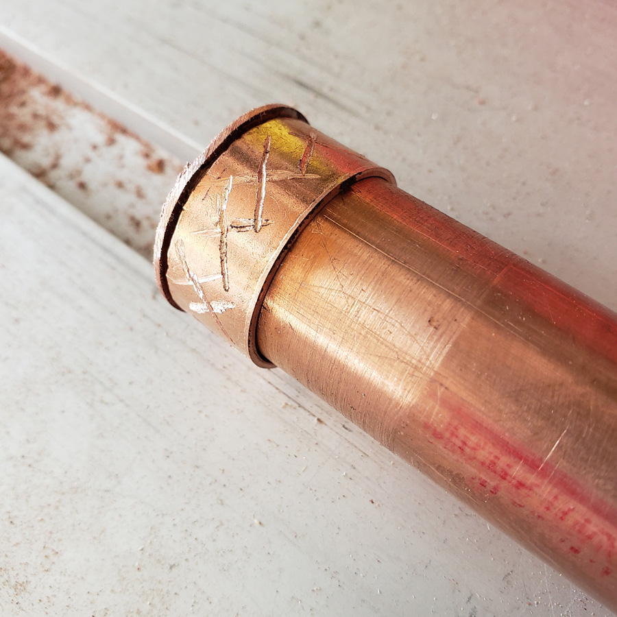
Here’s the final result.
After the sanding down I cleaned the piece. Next I cut the end off using my tubing cutter. The end cap was marked in preparation of drilling a hole in the center of the plate.
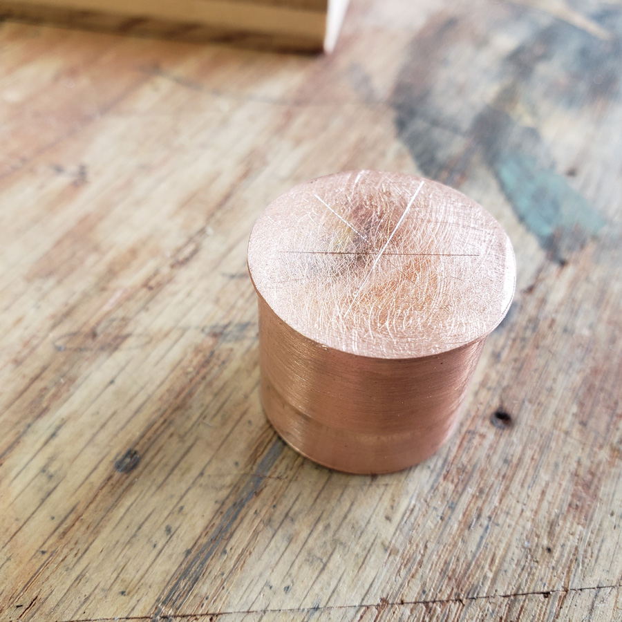
The copper “plug” appears sort of like the brass end of a shoygun shell.
More coming……