On turbo the green is more of a yellow green. No question that it out throws the white. Color rendering would not be good, but I have no trouble seeing wildlife even at distance. If the tint had been more of a green laser green it actually wouldn’t be nearly as useful. I actually started taking out to see what was out at a distace over the white w1. That was up until I got the 90, my favorite, because it lights up everything even thought it is clear that it doesn’t reach out quite as far.
If the white W1 is tweaked to 4.9 amps turbo and I swap in a green W1, it appears from djozz's tests here: https://budgetlightforum.com/t/-/56233, about 7 amps would be the ideal level for turbo.
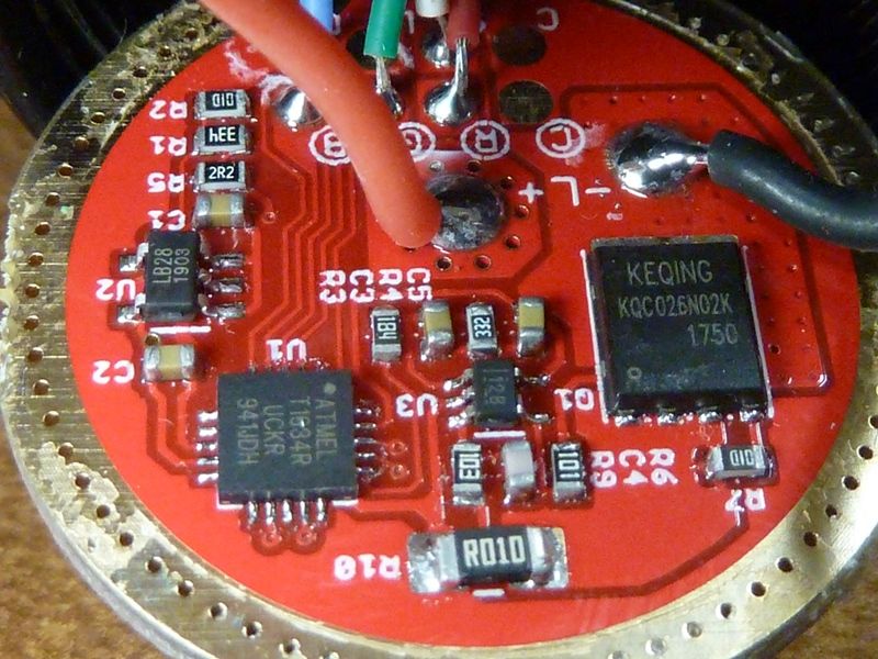
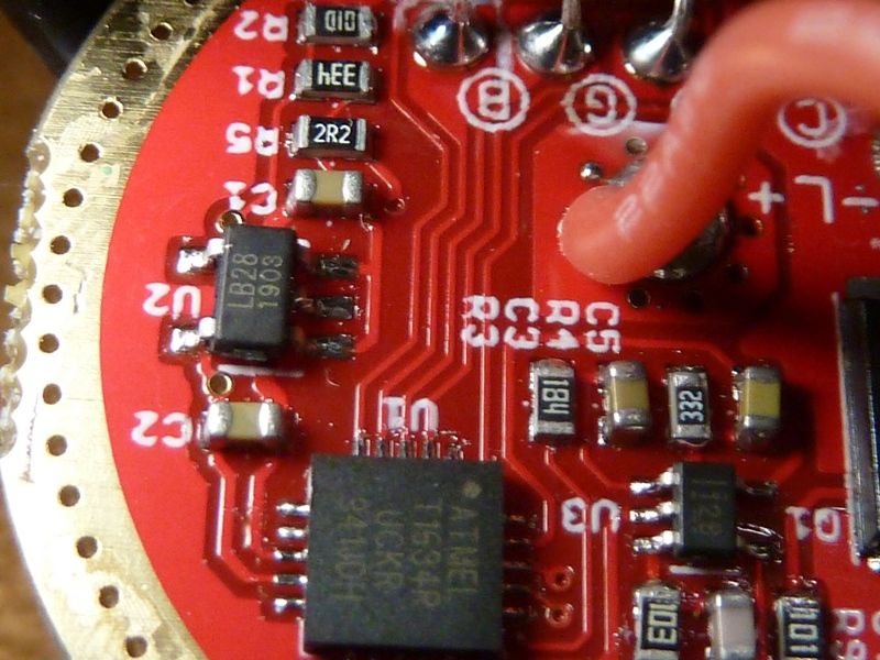
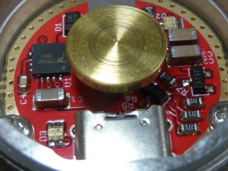
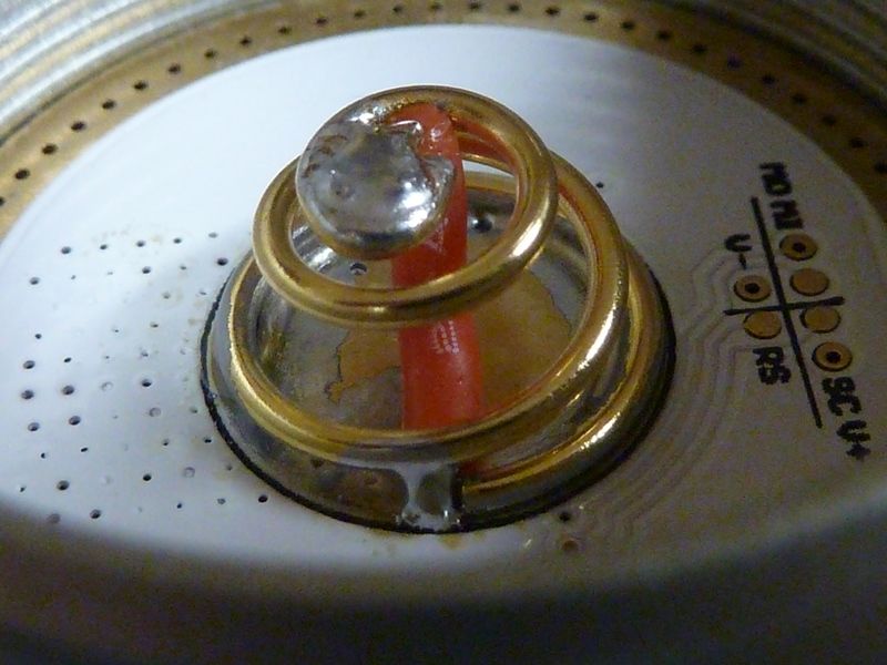
So, anyone know how the K1 driver can be tweaked up? Here's a couple pics of the driver:
I reviewed TK's cfg and hwdef files for the K1 and it shows one channel of output only, and turbo is set to full scale at 1023. PWM is used to control an opamp, not the LED output directly which makes sense for this kind of driver. So I don't see any way to bump amps from the firmware - must be a hardware mod/change.
I'm guessing it's an R10 swap, to a lower value, but not sure.
I could try asking/reaching Hank I guess.
I know pin #16 (PB3) is PWM output to the opamp to control the brightness level. Not sure if U2 or U3 is the opamp.
Yeah, it’s a sense resistor mod. Not sure which resistor or which value, though. R10 is a good guess but I can’t confirm it.
Pretty sure that U3 part is the opamp, and the U2 part is a diode or LDO thing. The R10 simply bridges Batt- input to the FET. I don't see anything else with the R10,so looks like current limiting and not sensing. Could still have a current sense resistor but maybe one of those other resistors around U3.
Dunno - I'm swapping the 22 AWG LED wires for 20 AWG and installing the green LED, then I'll take amp and throw readings.
U3 is the opamp, R10 the sense resistor. There’s a trace between R6 and C4 to the opamp. You can swap wires as long as you want, the current will stay the same. Not sure if there is a bias in the opamp, that area is hard to see in the pictures.
Well it's not a boost driver, so won't the output drop as the batteries drop at some point, and lower resistance in the circuit will put off the drop longer? the green W1 has a higher Vf than the white so it's more relevant? Dunno, seems logical to me.
R6 does go to the FET gate. Would be nice to have the datasheet on that opamp, and the U2 part for that matter.
I know just enough to be dangerous, no more... 
Been bizy with other things, gonna go finish the green LED mod and check results - amps/throw.
I’d love to give a more useful answer, but I don’t know enough about circuits to know how to mod this one. Someone designs it, chooses pinouts, and makes it respond appropriately to a PWM signal… and it’s mostly black magic to me. I just put a robot in the driver’s seat and teach it how to use the steering wheel. So I don’t have to know much about how the engine works.
I’d probably be tempted to just draw a graphite line across the resistor to see what happens… but that could potentially kill the LED. So I can’t recommend it.
No prob TK. Just makes me appreciate working with DEL on the Q8 and BLF GT - he detailed and explained things, published it and never sounded condescending (though he could have with my stupid questions ). I do miss him here on BLF...
Anyways, after the mod the tail amps was 4.85 amps dead-on steady, as expected (no mods yet). Little surprising the throw #'s were pretty much dead-on with what the white W1 I measured. The white W1 measured 655 kcd and the green measures 652 kcd, both taken at 5 meters, same meter. At first the green measured 627 kcd but noticed it was slightly off center. Loosening the bezel slightly actually made it better centered - could see it looking at the LED, and looked better centered with the beam. So centering got a bump from 627 to 652 kcd. I think the 4 screws of locking the MCPCB in place can cause centering problems because the reflector can't apply any force to center it.
The lumens got a little bump. Now I'm wondering how Hank got 720 kcd, did he mod the driver to get more amps from the green? We know it can take more amps.
Think'n bout this more, we know lumens and kcd scale the same, and am getting bout 8-9% more lumens with the green, so wondering if there's a focus problem.
Yes, lowering the resistance makes it regulate a bit longer, efficiency should stay almost the same (moves some losses from the wires to the FET).
I think I was wrong with my analysis. Here is a quick drawing of that part of the circuit. Don’t ask me why there’s R7 as a pull-down.

Yea, been researching this more online on stack exchange (Here and Here). That R10 is a 0.01 ohm resistor: dang that's small! Doubt I have anything that small that can take higher currents, I'm assuming it needs to.
Just emailed Hank if he may know if the driver is configured differently for the green LED to get the higher 720 kcd throw #.
I’m pretty sure there are different drivers for different currents.
I’m aware of at least two versions of the K1 driver, with different sense resistors for different currents. IIRC it’s about 5A for W1, or 8A for W2. A similar trick is used on the KR4/KR1 driver’s 5A linear circuit.
There’s no firmware difference, and the driver is identical aside from the resistor value. It just has one component to tweak to adjust the maximum flow.
Yep, I see your cfg and hwdef files for the SBT90.2 (wide open) and the XHP35 HI (12V) versions. The 12V and SBT90.2 versions could be different designs, but maybe same core design - we don't know. I'm sure Hank had someone design them. Gotta check my stock of sense resistors. I know some of them are pricey, like $1+ each.
OK, Hank responded - said changing R3 will increase current. I assume that a lower value would - R3 is 180K ohms.
Sorry if this has been answered already, but is there a way to change the brightness of the aux LEDs while the light is on? They’re way too bright for me.
Not without changing the source code. At the moment, it’s hardcoded to display battery voltage while on, using the brighter of the two button LED levels.
But if you have the reflashing kit, the code is open-source and there are people willing to help with understanding how to modify it.
Makes sense. Some kind of biasing with a voltage divider.
Updated circuit diagram. Some guessing involved.

OK, so swapped the 180K R3 for a 100K - now getting 7.6-7.7 amps at the tail - little overshoot, but decided to test it anyways.
Throw went up from 652 kcd to 712 kcd, lumens from 885 at start to 960 at start (calibrated #'s).
So what else could be keeping the throw # down? Still well centered, good looking hot spot. The centering piece - it's a bit high, and the style of have a curved cup around the LED, and it's colored white. So decided to sand it down a little:
- base from 0.96 mm to 0.85 mm
- sanded top down - took off 0.03 mm (little)
- overall height from 1.83 mm to 1.69 mm
New numbers:
- 725 kcd (1703 meters), taken at 5 m
- 996 lumens at start, 954 lumens at 30 secs (temp calibrated, raised max)
As you can see, it doesn't drop much over 30 secs, and the droppage slowed down to a crawl at 30 secs (expected for this kind of regulated driver). Lumens is quite lower than what djozz measured, but could be from several things:
- maybe I got a lower bin LED
- my cheaper light meter may be under measuring green
- my PVC lightbox may have issues with throwers
- etc...
Now it's performing to Hank's spec. I would experiment with the centering piece more, but I got no backup, so afraid I'll make it worse then have no way to go back.
A resistor value of 120K for R3 may be ideal for this green LED. These are 0603 sizes.
4.8 -> 7.6 for change of 180K to 100K. If it's somewhat linear, 120K should be about 7.0 amps which is the peak on djozz's chart. Hhmm - might have to go with that. I bought a huge collection of 0603 resistors so I got a ton of sizes and about qty 50 of each size.
Ok, the 120K R3 resistor is installed - 7.21 amps now on a 40T, better. #'s got a little bump as well, so guess the 7.6 amps was over the hump.
New numbers w/120K R3:
- 730 kcd (1709 meters), taken at 5 m
- 1002 lumens at start, 960 lumens at 30 secs (temp calibrated, raised max)
My stock K1 SBT90.2 on a fresh 30T at 4.20V:
- 19.1 amps at the tail
- 510 kcd (1428 meters), taken at 5 m
- 4800 lumens at start
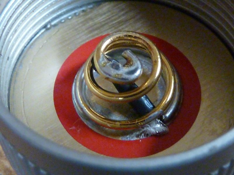
After adding 20 AWG bypasses to all 3 springs on the SBT90.2 K1:
- 22.3 amps at the tail
- 520 kcd (1442 meters), taken at 5 m
- 5358 lumens at start
Not sure why I didn't see a bigger bump on throw - could be my 510 kcd on stock was high (the 30T helps btw). Forgot to de-lens the LED - should add about 5% in kcd and lumens, so should be ~545 kcd, right where vinh claimed for his mod.
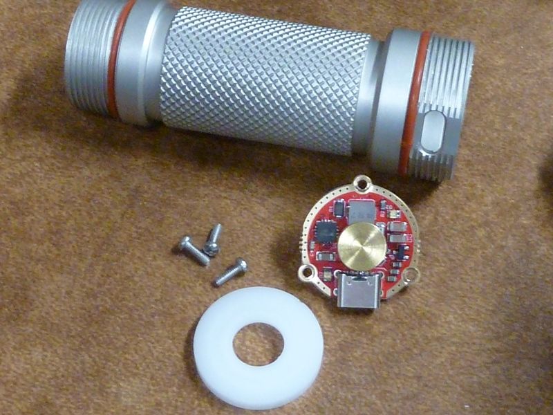
Bypass mods on the SBT90.2 version. What the USB-C charge circuitry looks like:
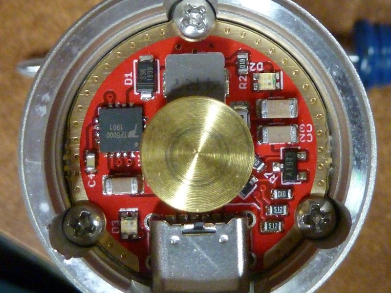
Bypass on the charge board:
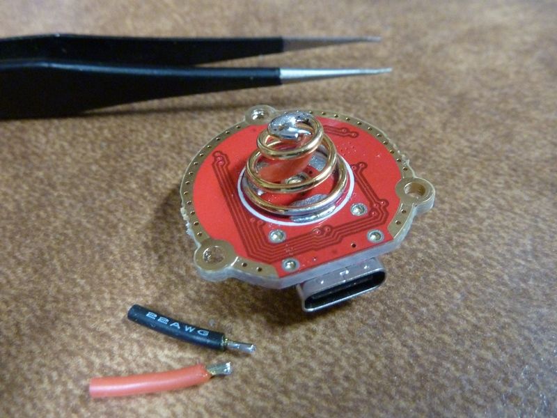
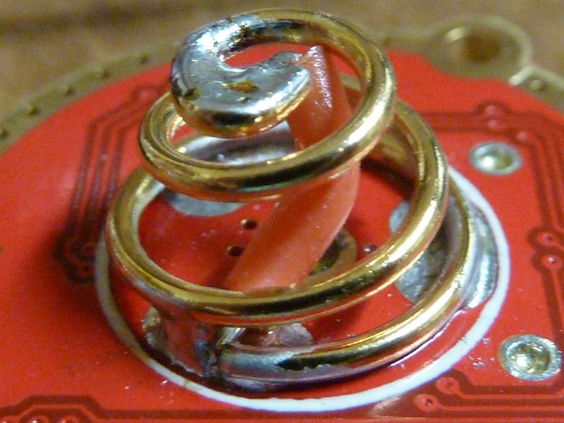
Bypass on the driver:
Bypass on the tailcap: