MtnDon's Hand Made Class, 8th Annual BLF/OL contest entry

A very simple thing … a battery tube liner.

The ID of the 3/4” copper tube is an actual 19.9mm. The cell I am using has an actual OD of 18.24mm. The cell is a sloppy fit. I used some of the laminated paper Shoji screen material that was last used in the Shoji latern contest entry. (2018, 6th annual contest). It has a textured plastic laminate on both sides of the patterned and colred paper.

I cut out a small rectangle about the same width as the length of an 18650 cell. It was cut long enough to allow a little more than a double wrap.

Then I rolled it up and inserted that into the main copper tube…

Ta-da!

The cell slips in and out nicely and does not rattle. :slight_smile: The textured surface of the plastic seems to make it stay in place without any adhesives or anything and when the cell is dumped out the liner stays in place. If everything was so simple…

That’s all for now, thank you…

I’m amazed you found the laminated paper. :slight_smile:

I almost didn’t :person_facepalming:
I knew I had some leftover material.
I was sure I had rolled it in two rolls.
I looked and looked and looked and could not find it anywhere.
Then after a day or two of puzzlement I found both rolls.
Tucked into the cabinet with my black powder supplies.
:person_facepalming:
No idea why I put it there.
But I don’t think I’ll ever forget now, so I left it there.

Don’t worry, if you’re like me, you will forget (by next week). That’s why i have nearly two of all my hand tools—where did it go? i know it’s gotta be here…quicker to buy another than dig thru it all.

And one week is like forever ago—they say your memory is the second thing to go, but i can’t remember what was first.

Nice work Don, and great write-down! That will be another wooden piece of art.

I hope to reach a moment in life that I could handle the amount of setbacks that you already had in this project, and overcome them just as stoic and gracefully as you.

I have lost track of how many in-process changes I have made on this project. The changes have not ceased yet, either as this update installment contains another.

Part of this was done last evening, part earlier today.

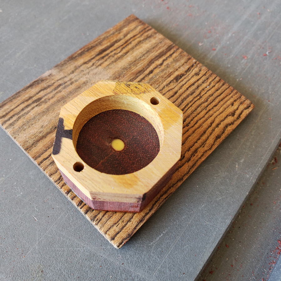
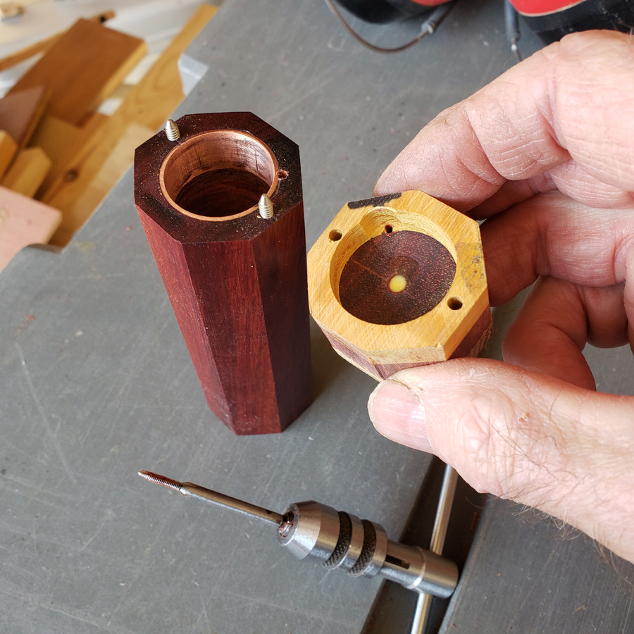
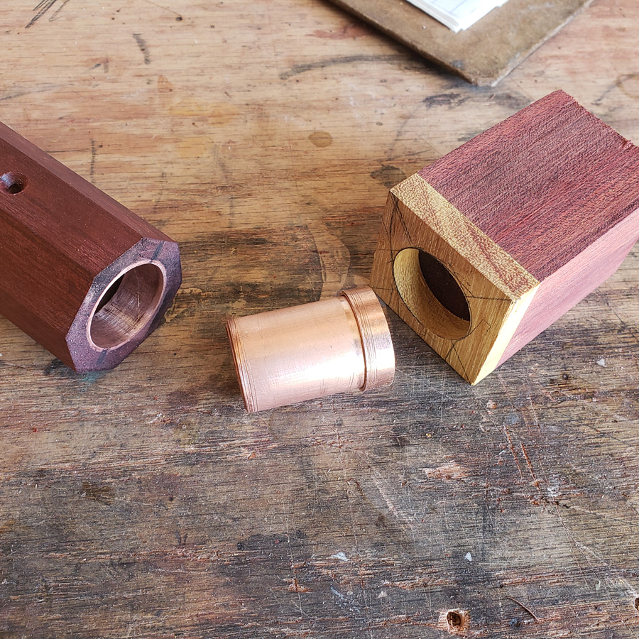
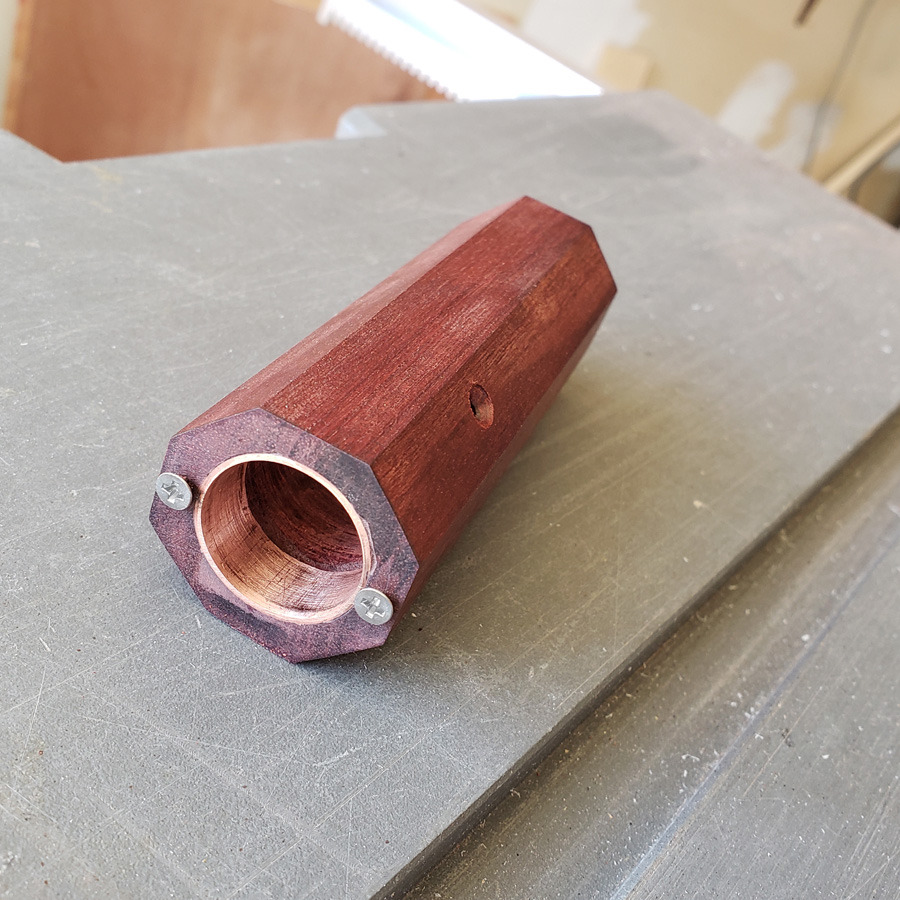
The next step is to make the tailcap. I had thought of making a longer body tube and cutting off a piece to use as the tailcap. That was not practical as my larger diamter boring bits are not long enough to bore a longer hole. Therefore, I need to make a cap that can be added on to the tailend. The picture below shows the body tube on the left and the glued up block of bloodwood with a osage orange cap. I drilled a 25mm diameter hole approximately 15mm deep in the capped end. The body tube is bored to 22mm. The longer piece of copper tube is approx 22mm OD and the short length is a coupler cutoff with an approx. OD of 25mm.

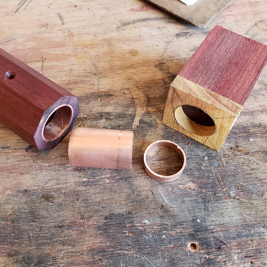
The copper pieces will act as an alignment tool

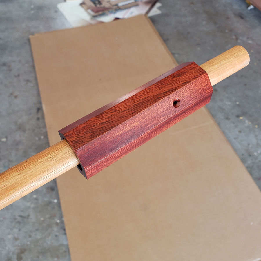
Here’s the body tube fitted over the copper and mounted to the face of the tailcap piece.

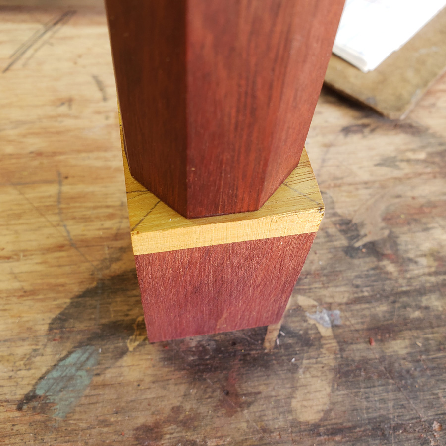
I pencil marked the outline of the hexagon shape. The black marker “T” is simply to indicate which side aligns with the body side screw.

Now I will take a few moments for some explanatory words.

When I make something of wood and want to be able to disassemble it at some point I often use wood screws. I believe this bloodwood is too brittle along the grain to use wood screws which tend to exert an expanding force when screwed into the somewhat thin sides of the wood body.

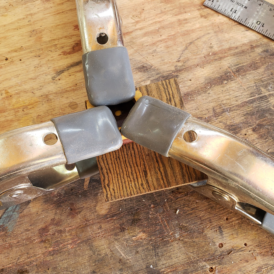
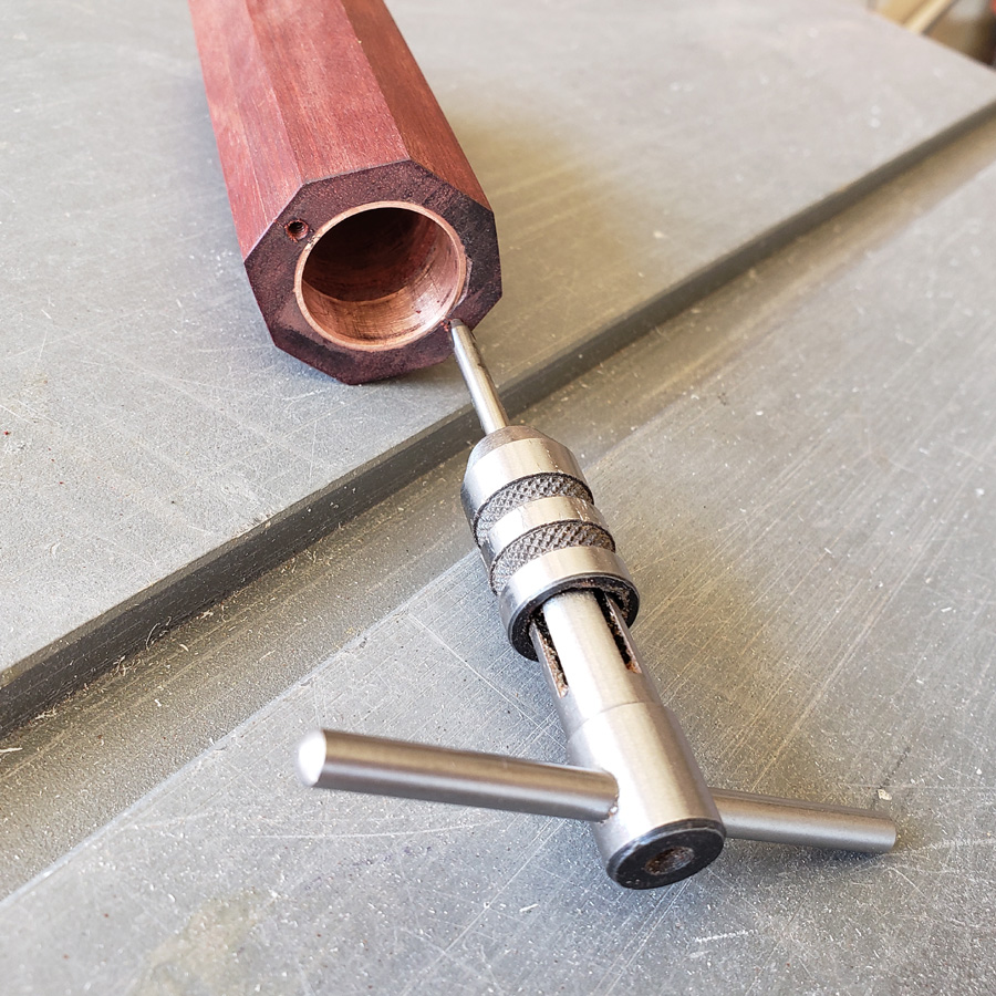
For an alternate method I have used threaded aluminum standoffs in past lights. These are internally threaded like the ones in the next picture. They are often used to mount pcb’s one on top of another. I drill a hole in the wood and epoxy the aluminum spacer/standoff into the hole. I had intended to use 2-56 threaded standoffs with an OD of 0.156”. However with the issues I have had thus far with the bloodwood I was concerned about drilling holes into the shell of the wood body tube.

Yet another idea came to mind yesterday. This bloodwood is very hard and dense. I wondered how it would work to drill and tap the wood with a machine screw thread. I hoped the tap would cut threds in the wood as it can in various metals. I also hoped that the density of the bllodwood was sufficient to hold threads.

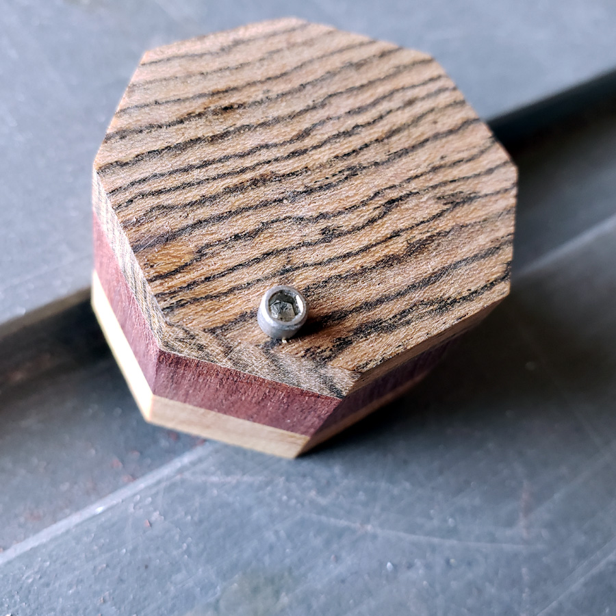
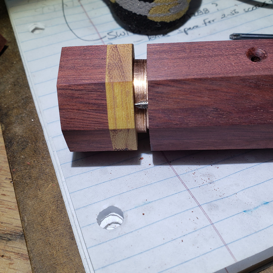
I drilled and tapped into the end grain of a glued up scrap. The smaller screw is 2-56 and the larger is 4-40. I took my time slowly turning the tap allowing lots of reverse twists to clear the cutting debris. The 1/4” long screws tightened up nicely and the threads held pretty good. I did manage to strip out the 2-56 with a harder twist.

I sectioned the block at the 4-40 thread to see what it looked like…

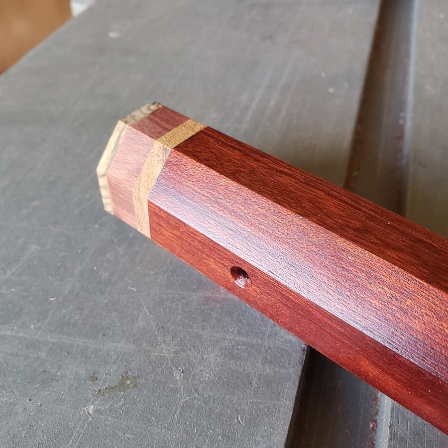
I drilled and then tapped two holes in the tail end of the wood body.

I was rewarded with two threaded holes and the body did not split or crack.

This is an awkward way to mark holes in the body and cap but it was necessary as the tailcap was still only a rough cut hexagon, larger than the wood body. Dimensions were somewhat irregular with too much danger of making an error and drilling a hole not quite in the right place if I first drilled through the cap piece and then into the body shell. It seemed better to drill the body holes and being able to place them right where I wanted them.

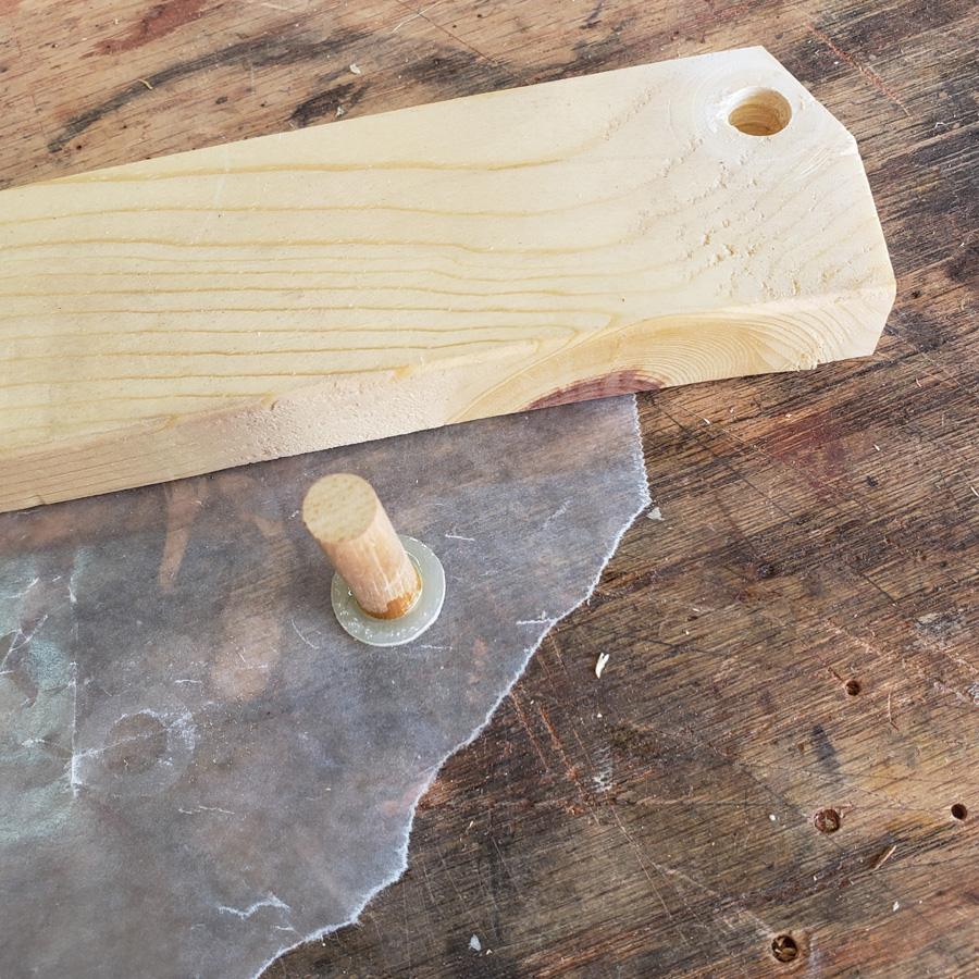
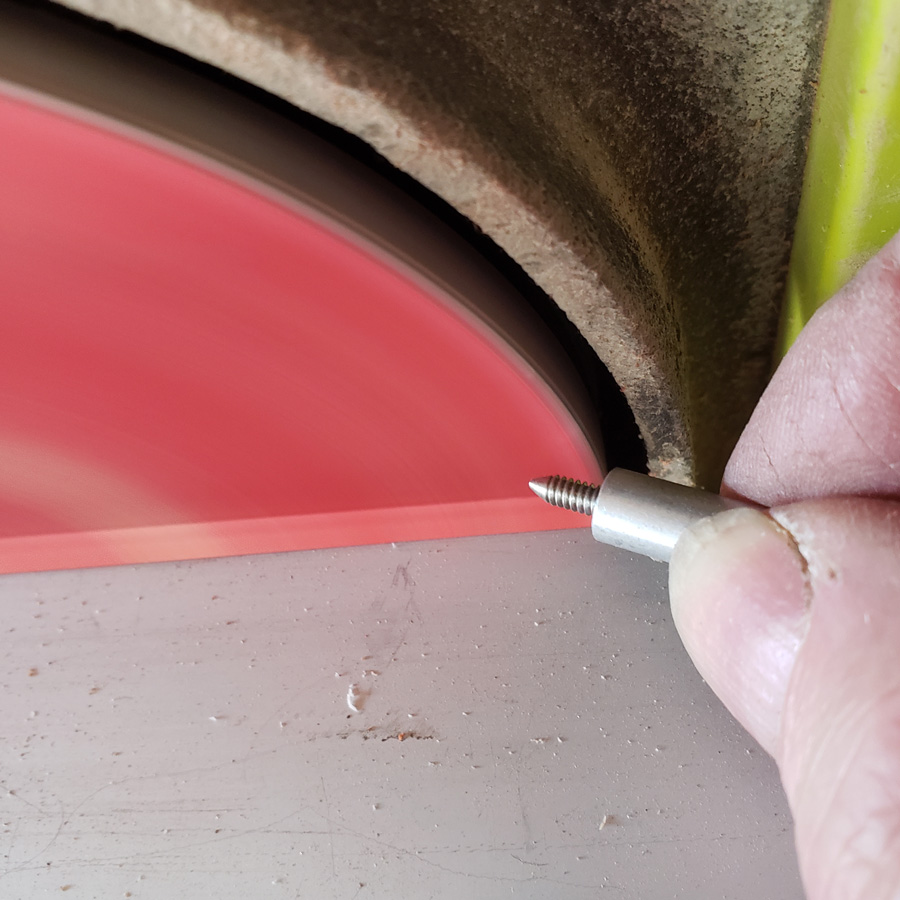
Then I would use “pins” to transfer the position in the body to the yet to be completed tailcap. For that I needed “pins” so I cut short lengths of machine screw. Using a threaded standoff as a holder I then sanded, or ground, a point to one end. I found that using the side of the disc that was turning downwards the threaded piece would self rotate as it threaded itself into the standoff. I had to stop and re-extend the rod many times.

Eventually I had two pointed and threaded pins. These were threaded into the body and then using the same copper tube pieces inserted into the large diamter holes as I used previously as an alignment tool I pressed the pins into the tailcap piece and was able to make marks for the centers of the two holes that would be drilled in the tailcap.

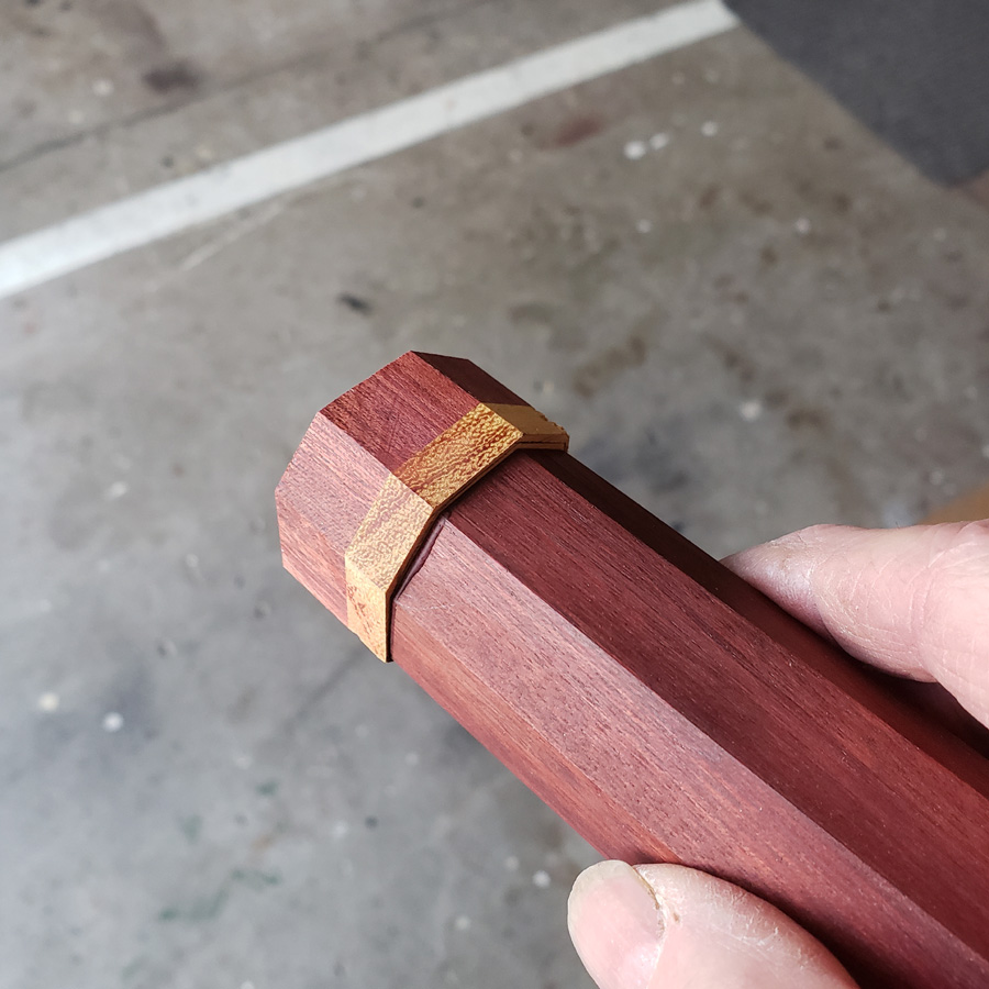
Does that all make some sense? The important thing to me is that it worked. I apologize for this next image. I forgot to take a photograph of how the pin alignment helped me. I realized the error after I had sanded down the tailcap. So when viewing the next image imagine the tailcap is still oversize, as it appears inn the two images that follow this one….

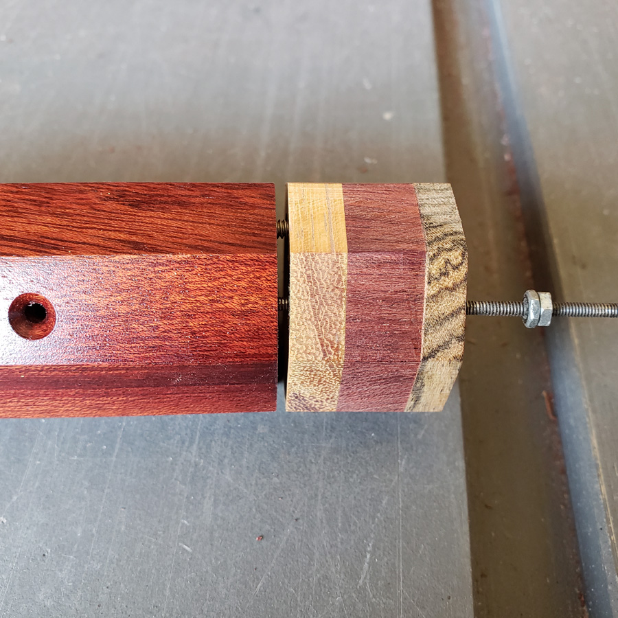
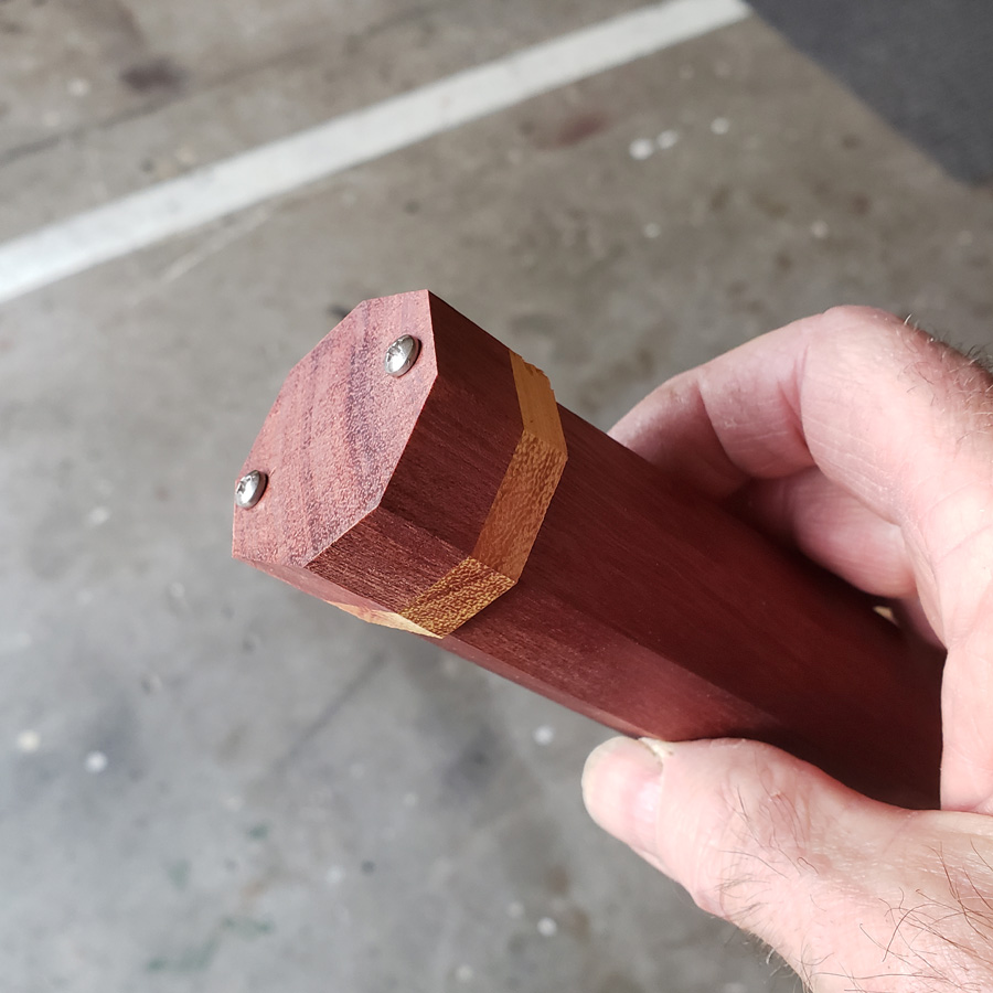
The next two images show the rough, oversize tailcap bolted to the body tube with two 4-40 machine screws.

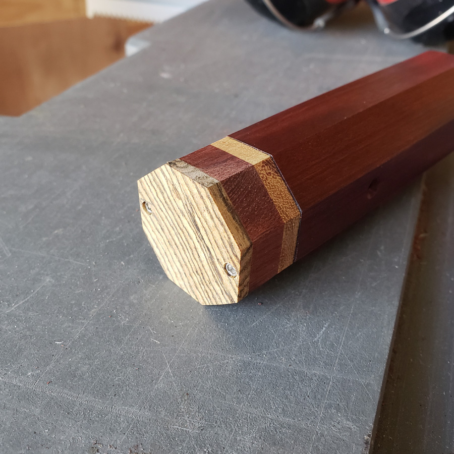
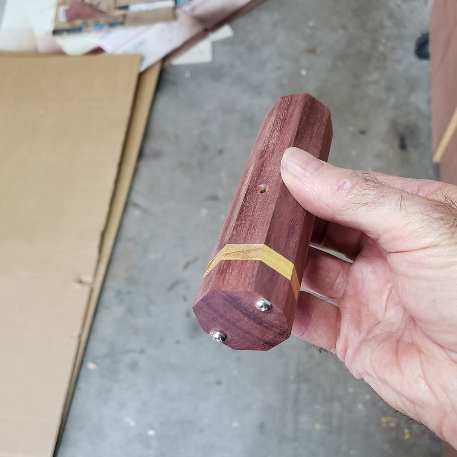
Then here is the sanded down tailcap and body unit…

Here is where I take a break. I’ll close for now with a photo of one of the wood curls in a drill bit. These are very hard to clear from the drill. They build up and if using a deft touch on the drill press quill I can feel resistance build up. I have to clear the bit every 1/4” or so. The wood debris/powder is packed into flutes of the bit so tightly I need to stop the drill motor and pick it out with the tip of an exacto blade.

It looks great, i like the contrast of the wood colors.

Is the wood very dense yet dry? Makes me think about trying to use a dull drill bit that won’t dig out a big ole chip (such as drilling into plexi plastic), but even little chips might not clear with dense wood.

Amazing that it takes to a tap and leaves a nice strong thread.

Before I get to the now commonplace, nearly expected, change of plans, here is a small piece that I needed to make for the tailcap switch unit. The switch will be recessed a little and needs an actuator rod. I made this from a piece of 3/8” dowel and a scrap of 1mm FRP. I made the FRP round using my sander jig apparatus. Then I glued the dowel into a 3/8” hole I drilled in the FRP and cemented the joint with some Kafuter UV activated adhesive.

I decided to give the body a coat of clear lacquer. My reason for doing it now was to keep the wood clean as it is being handled a lot at this stage.

I used spray lacquer and a wood dowel to hold the body piece.

Now for another change. I forgot to take a photograph of what caused this change. Way back, when I made the head of this light I used two machine screws through the head to secure the head to the heat sink and front copper disc. I planned on using a similar system to secure the tailcap to the tail end of the wood body. I had a memory lapse. I didn’t double check :person_facepalming: , but I thought I had used 4-40 socket head machine screws for the front. The socket heads were fitted into two drilled recesses to alllow the machine screw heads to be flush with the surrounding wood surface. Alas, I has used smaller 2-56 machine screws. The 4-40 machine screws have a larger diameter head. That head OD is large enough that the desired recess holes would cut into the perimeter, would break out of the octagon side of the tailcap.

An aside thought… this light should be thought of as a prototype I suppose. (A prototype is an early sample, model, or release of a product built to test a concept or process.)

I gave some thought to not recessing the heads, or to using flatheads instead. However the flathead countersink would run into the same problem of “not enough meat in the edge to allow it to work”. With only two screw heads protruding it would not be possible to tail stand the light. I thought of adding two more machine screws, but gave that up as protruding screws at the tailcap would conflict visually with the recessed heads of the front end.

The solution I came up with was to use 2-56 screws on the tailend. To achieve this I cut a new cap piece to glue over the 4-40 holes in the tailcap. I would drill new holes in the octagon face edge one section over.

So, here’s a new piece of bocote being glued and clamped…

The finished cap with the bocote was sanded down to an octagon shape. I also cut down the bloodwood length before gluing the bocote cap on; no need to have such a long tailcap.

I used the two 4-40 pins to hold the tailcap in position while I drilled the first 2-56 sized hole through the tailcap and into the bloodwood body tube. I did get close enough to the epoxied in place copper tube insert that the threads actual are cut into the side of the copper as well as the bloodwood. And I had to cut a recess in the inside of the cap as the position of the hole was such that the hole wanted to drift when being drilled. Anyhow that is hidden, right! And it is a prototype.

With the first 2-56 machine screw hole completed I trial fitted the tailcap. The 4-40 locator pins are visible. I did not have a long enough 2-56 machine screw on hand but I did find an old length of 2-56 threaded rod.

Here’s a short 2-56 socket head screw trial fitted.

After drilling and tapping the second 2-56 hole I recess drilled and test fitted the cap to the body. The screws I had are not long enough for final use, but I have some longer ones coming. The screws pictured are only about 1/8” into the tapped holes. That is insufficient grab to last I figure.

I clear coated the tailcap after removing it. Prior to clear coating I drilled the center external recess for the switch actuator rod assembly. I’m using the same diameter dowel rod to hold the tailcap for spraying as I used to make the actuator which is also displayed.

When the switch does arrive I will fit it and then trim the actuator rod and make whatever adjustments may be required.

Till later, that is all for now.

The switch is still someplace between China and here, heading in this direction, I hope.

Yes. Thanks you, I like using different contrasting woods.

It is dry; the moisture meter reads 6%. But at the same time it seems somewhat oily or something as it does not come out as powder. More like compacted powder with some sort of a binding agent. The little curls don’t turn to dust readily when squeezed. It is odd wood. Nice color though.

While you’re waiting on the switch let me throw in a piece of wood and a nutty story with you.

For several years i have been drying out some pieces of pecan and black walnut that i quarter sawed on the hillbilly sawmill (chain saw). i was interested in finding a piece that might show up with some tiger stripes in the grain so i kept this section of black walnut with dark and light colored bands and the bulging knot. i have no idea what i’m doing, it’s just about having fun.

So this past weekend i pulled it out of the shed and set about to cut some blocks and pieces with another precision hillbilly tool, the electric skil saw. Well that’s when i discovered what caused the bulge in the tree, what a surprise:

That’s nuts, for you. :wink:

It is nice to be able to use some locally sourced wood. Unfortunately to do that to any degree one really needs lots of machinery so large logs can be moved, sawn, dried and ultimately used to build something. A friend has a small saw mill based on a large circular saw turned by an old Massey Ferguson tractor; the blade is something like 45 inches I think. We have predominantly pines and firs, no hardwoods other than Aspen.

I’ve given this light a name; MD4W

MD = MtnDon
4 = 4 emitters
W = wood

Just like the FW3A, which was the inspiration for the name, the tailcap is not really meant to be removed, but can be. :wink:

Very nice MD. what do you do with your creations?

I have used last years as a walking light, as it was intended. It will see more use as the daytime hours shorten through fall and winter.

The Shoji lantern from the 6th annual contest was gifted to my son. It fits right into hos decor as he has a set of bookshelving with sliding Shoji style panels for doors.

The entry for the 5th annual contest was gifted to a sister.

The 4th annual contest entry has a place on my “special things” shelf.

All very nice.

I am not a wood expert but i think that if you plan to open these screws often, threaded insertions will be more robust than tapping the wood.

I agree. However the problem is two-fold in this application. The outer diameter of the insert is too large for the thickness of the wood and that type of insert cuts its own threads as it is screwed into the wood. The force would almost certainly cause this wood to split. I have used those inserts before. They can be a real problem to install in wood other than the softer varieties like pine and spruce.

I never intended the tailcap to be removable in ordinary everyday use. The bayonet copper coupling at the head allows for cell change, so very much like an FW3A there will be no reason to remove the tailcap assembly for daily use. I could have made a second bayonet system at the tail, but it did not seem to be necessary.

I appreciate the thought, comment and link. I hope that it works out okay. If there was to be a second one made I would use a different wood species or come up with some other solution…. maybe a little thicker body wall and use the epoxied into place aluminum inserts. Those are a smaller diameter than the threaded inserts.

I have used some other woods that are about as hard and dense but do not split as easily as this bloodwood. I would be better off with it. It’s a nice enough brown with darker streaks in the grain. However, I do like the color of the bloodwood a lot. I never used bloodwood before this.

Looking good Don. :slight_smile:

I am by no means adept at making things from wood but did find these when I made a wood, aluminium and brass torch.

https://www.google.com/search?q=Cap+Head+Wood+Screws&source=lnms&tbm=isch&sa=X&ved=2ahUKEwj9ievVg6vsAhXw7HMBHY3LD6IQ_AUoAnoECBYQBA&biw=1278&bih=959

I like the looks of these from that search link , but need a smaller size package. :wink: The point with the notch cuts the wood fibers as the screw is turned.

They are used when installing cabinets (as in kitchen…) and I never thought of them at all. I do have some here someplace.

I should try one in a scrap of the bloodwood and see what happens. Thanks.

I hope they are not attaching kitchen cabinets with finish head screws. :frowning: