Thank you. Nice response.
I see all the 80°c ratings on this cell and was wondering, I’ve got a project going into my roof is probably 60-70°c max in summer (Australia) I checked today with IR thermometer it was 55. I’ve been researching what battery to use, the best I’ve got is an lgaahd2c1865 which says it’s rated discharge temperature is 70°C in the data sheet, that one’s from a dyson vacuum battery pack. All my other cells I could find data sheets for were only rated for 60°C.
My question is I’ve basically got 150uA continuous standby current and maximum 1a draw for maximum 10s once triggered, given your experience heating cells for fun do you think I’ll have problems with my single cell venting in my roof. Do you know of any high temperature tested cells other than this one? Any thoughts on long term operation of cells in high temperature… I imagine it will degrade capacity faster. Appreciate your input!
Officially I would not recommend it, if it is a small project, you might consider using some eveloop AA cells instead.
Un-offically I leave some flashlights with cells in my car all year round and it can get up to ~120-140f in the summer in there. I have not had any issues and they hardly even self-discharge. I generally charge them once a year and they are normally still above 4V if I did not use them.
Cheers Texas, I did think about that but eneloops are only rated for 50°c and as it’s my electronics design… It won’t work well off 2 AAs, low battery alarm kicks in at 3.1v, and I can’t use any buck/boost for the standby as it took me ages just to get the standby current that low, I’d never get close to it with a dc-dc converter. What’s the worst that could happen, with a high quality cell it’ll just vent and I’ll have a dead battery… Probably. I’m hoping someone might have some tips for higher temperature rated or safer chemistry but still 3.7v nominal battery…
could you run 3x AA cells? It would only be 0.3V higher charged voltage.
If you put the cell in some kind of metal case that would protect any fire from escaping yet not turn into a pipe bomb, then I suppose it could work, really depends on your attic and how flammable it is.
I would basically plan on the cell venting, if you would not feel safe with it actively venting, then I would not use it.
I could but I'm not certain how much safer would really be. Given the rated temperatures on the cells, I would definitely exceed the ratings on the eneloops but I would not exceed the rating for the vtc6 or the Samsung 25s /25r, I would probably not exceed the rating for my lg cell (70°c). I had a bit of a fish around for data on eneloops behaviour at elevated temperature but couldn't find anything. Lions however I found this paper which shows thermal runway onset temperature for various charge states, cells that are not overcharged all went into thermal runway over 140°c which leads me to believe the data sheet. Unfortunately they didn't actually state which cell they tested.
Like I said I think you will be fine with the 18650 cells, I would just build it to handle a possible venting.
Sorry for necroing…
I just got two VTC6 that measure internal resistance of 47 and 67 mOhm on 1a discharge in my MC3000 charger. From what I read here it should be <<40mOhm. Did I get second-grade cells?
Update: Looks like MC3000 only measures IR in the beginning of the cycle. After dropping 400mAh, I restarted discharge and it measured 30 and 43 mOhm already. Does it make sense?
Yes. Battery chargers actually don’t measure Internal resistance correctly.
Yes, but it do not eliminate problems with contact resistance.
You mean resistance of the charger terminals?
After some more tests, it behaves as follows - I place VTC6 in, say 1st, slot. Start discharge. MC3000 measures IR about 50mOhms. About 200mA down, I restart the discharge program. MC3000 measures the IR again on start and now it’s down 5-7mOhms. Eventually when the battery was about 3.9v, IR stabilized at ~30mOhs, which is what is reported in the beginning of this thread.
So does IR changes (decreases) with discharge? Again, I was not touching battery/charger in that experiment - only stopped/started discharge program through the app.
HJK, I have read your IR measuring post [1] and it made me even more puzzled - you say IR increases as capacity drops, but I see the opposite. Unless it’s the temperature rise, which I doubt, since it was 1A discharge for ~30 minutes total and the battery was cold to touch (room temperature).
Ideas?
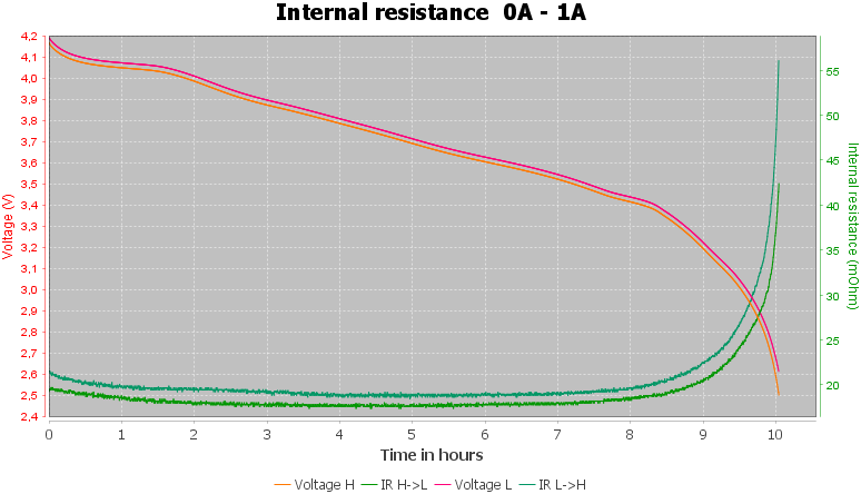
IR do not increase before the battery is nearly empty, here is a curve from another battery:
Aha. OK, that still leaves the question why in my case IR value decreases as I pause and restart discharge cycle.
(HJK, if you think this comes to lack of knowledge on my side to understand this, please say it and I’ll stop bugging you ![]()
Probably the contact resistance that changes a bit, some of it can also be from a temperature increase.
Are these VTC6 flat-tops and relatively new?
Try to clean the contacts on the MC3000 slots and also clean the VTC6 top & bottom first.
Then seat the VTC6 on the MC3000 slot.
Press both the UP and DOWN keys on the MC3000 simultaneously, it should show the IR readings,
try to do it again while rotating the VTC6 cell and check if the IR reading changes significantly (usually it will change slightly for flat-tops, since rotating it slightly may make the contact slightly better or slightly worse, at least from my experience with my MC3000…
If I recall correctly, a good VTC6 will generally register somewhere around 25mOhms reading on my MC3000 (assuming the VTC6 is not very discharged, and not a really old/used up VTC6)
Yeah, flat top and less than 10 cycles. Purchased several weeks ago (doesn’t say anything about their real age obviously).
Thanks for the hint about IR measuring shortcut - very handy!
I did some more tests including cleaning, rotating, etc., and results are below.
I got 2xVTC6 and 2xMJ1 from source A and 2x40T from source B.
both VTC6 and MJ1 on MC3000 show much higher, 20-30mOhm more on MC3000 when fully charged compared to highly discharged. Doesn’t happen with 40T - just 5mOhm variance.
Here are the details:
VTC6 1: 70mOhm at 4.21v <—- last charged with Lii-500S
VCT6 2: 35mOhm at 4.01v
When I charged them last time they started at 3.5v and both measured 32mOhm.
For comparison I have 2 pieces of 40T and they both measure 18-230mOhm regardless of the charge level:
40T 1: 20mOhm at 4.14v
40T 1: 24mOhm at 4.25v <—- last charged with Lii-500S
40T 2: 18mOhm at 3.73v
I then tested a pair of LG MJ1 and they show:
MJ1 1: 65mOhm at 4.14v
MJ1 1: 85mOhm at 4.23v <—- last charged with Lii-500S
MJ1 1: 55mOhm at 4.09v
MJ1 2: 70mOhm at 4.18v
MJ1 2: 53mOhm at 4.08v
All of the batteries were purchased during the last month and have less than 10 cycles on them.
What worries me is that when charged with Lii-500S they end up with more than 4.2v voltage. E.g. I measured voltage using all my instruments on VTC6 last charged with Lii-500S two days ago and got this:
MC3000: 4.21v
Lii-500S: 4.19v
Nitecore UMS2: 4.19v
eevblog BM235 DMM: 4.213v
Uni-T UT216C DMM: 4.207
Higher-end instruments show that battery’s voltage is above 4.2v. Does Lii-500S overcharge the batteries a little bit? I see that MC3000 by default won’t even start charging if the voltage is above 4.15v and once the charging finishes, the voltage drops to 4.17-4.18, while after Lii-500s it stays on 4.2v (and more as I see now). Topped up again my MJ1 from 4.14v to full on Lii-500S and once done, the battery voltage is 4.237v according to DMM and 4.23 at MC3000. And again with 40T on Lii-500S at 2A which ended up with 4.25v!
Is that Lii-500S safe at all?
EDIT: Found HJK’s review on Lii-500s [1]. I’ll ask him there: Test/review of Charger LiitoKala LiitoKala Lii-500S
Hi, there. I am interested in understanding how you considered reaching of thermal cut out (80°C or rather 91°C) by testing the VTC6 cells at 20A and furthermore 30A. In the plotting chart it is possible to guess reaching 55°C (supposed on the external surface by LM35 you mentioned in the test setting page).
I am guessing you should have a thermal resistance value to determine this 91°C.
Thanks in advance. Regards
The temperature scale shows temperature increase, you have to add around 25C ambient to that. My log show the measured temperature and works to above 100C, but when drawing the chart I subtract the ambient and limit the scale.