Hrmm…I was thinking more along the line of the chalk white of the Tool AA. Similar to what kawiboy posted. That and red aux led Mmm…delicious.
Apparently red GITD isn’t very bright.
Does anyone happen to have one of the #36 o-rings laying around they don’t need? I did the o-ring mod on all but one of my FWs, I ran out of them! It’s not that they’re expensive, my OCD will give me a lot of trouble if I buy a pack of 10 and leave 9 lying around. Would be nice to just get the one I need, I can PayPal you the cost of a stamp and envelope! If not, no worries….
I have a pack with 7 remaining. Just PM me your address.
Okay, another question… does anyone happen to have an FW3A 18650 (yes 18650) body laying around? I have a mod-fodder FW3A that I got with 18350 and 18500 tubes, but no 18650 tube, and I’d gladly purchase yours. Send me a PM if so!
CPFs favorite diffuser (a disposable water bottle cap) fits on the FW3A.
Has anyone seen or forged a magnetic tail cap? I mean not something bolted on to the end using 3D printing, but as a standalone integrated metal solution. I’d be really interested in seeing it or purchasing one if someone has. Thanks
lol is that “tactical” enough for them?
Kinda surprising nobody has melted a bottle cap onto the head of their light there yet if it’s popular.
Good day, does anyone know the o ring size used for the battery tube (switch end)? And the white oring too.Thank you
what is this??? how did you do this surface? very cool.
Looks like just sandblasted aluminum to me, I like it.


Nichia 219 4000k secondary
Xlp hi 6000k main beams
work done by me
idea done by contractor
Big thanks to contractor
Very clever mod there :+1: how do you switch between the 2 modes? is it a custom firmware thing?
Firmware is flashed for use of secondary’s yes
Dbsar had a chalky white one iirc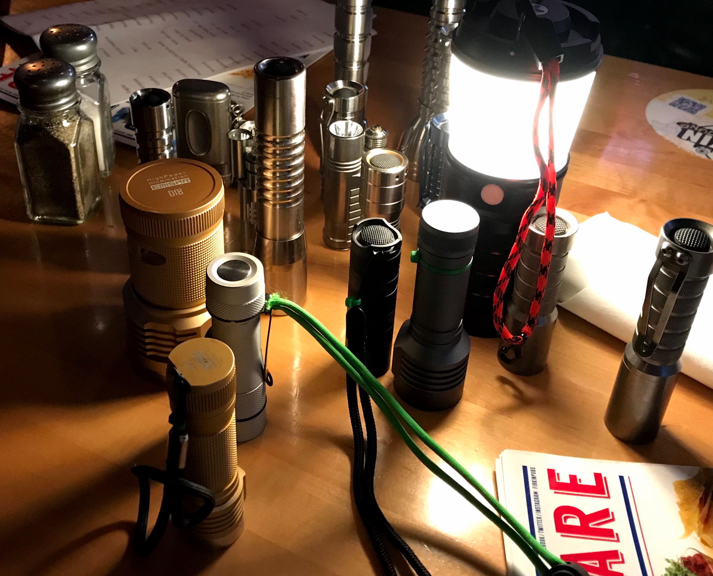
does this work for the FWAA switch button, and which O ring size would you choose?
I haven’t checked the difference between those o-rings.
However, I can confirm that the space inside the button boot and the top of the switch in an FWAA appears the same as in the FW3A. I have a large bag of o-rings and every one of my FW3As and FWAAs has received the o-ring mod using the same o-rings.
Basically, any o-ring mod that works on an FW3A should also work on an FWAA.
thank you ![]()
I assume the o-ring goes inside the base of the button?
The oring mod is quite simple:
- Disassemble the tailcap
- Remove the plastic nubbin from its socket on the inside of the rubber button boot.
- Place the endcap on a table with the inside facing the ceiling.
- Insert the metal button
- Insert the rubber button boot
- Insert the o-ring into the rubber button boot
- Insert the switch PCB.
- Insert and screw on the switch retaining ring.
Note that the FWAA has a small wide spring that sits around the outer edge of the button boot. It provides electrical contact even if the switch pcb is not snug. Make sure this is in position when reassembling. The FW3A does not have this spring.