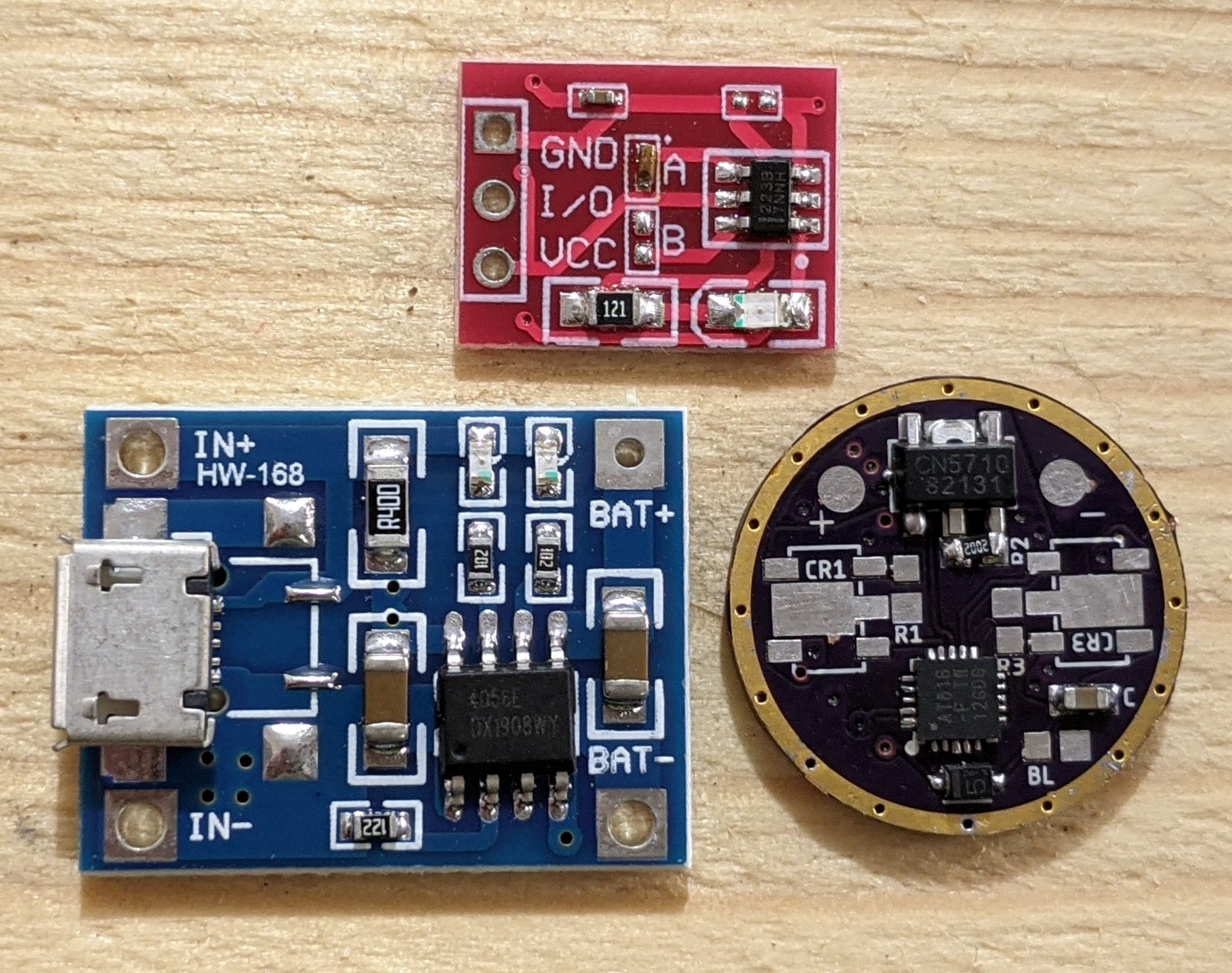
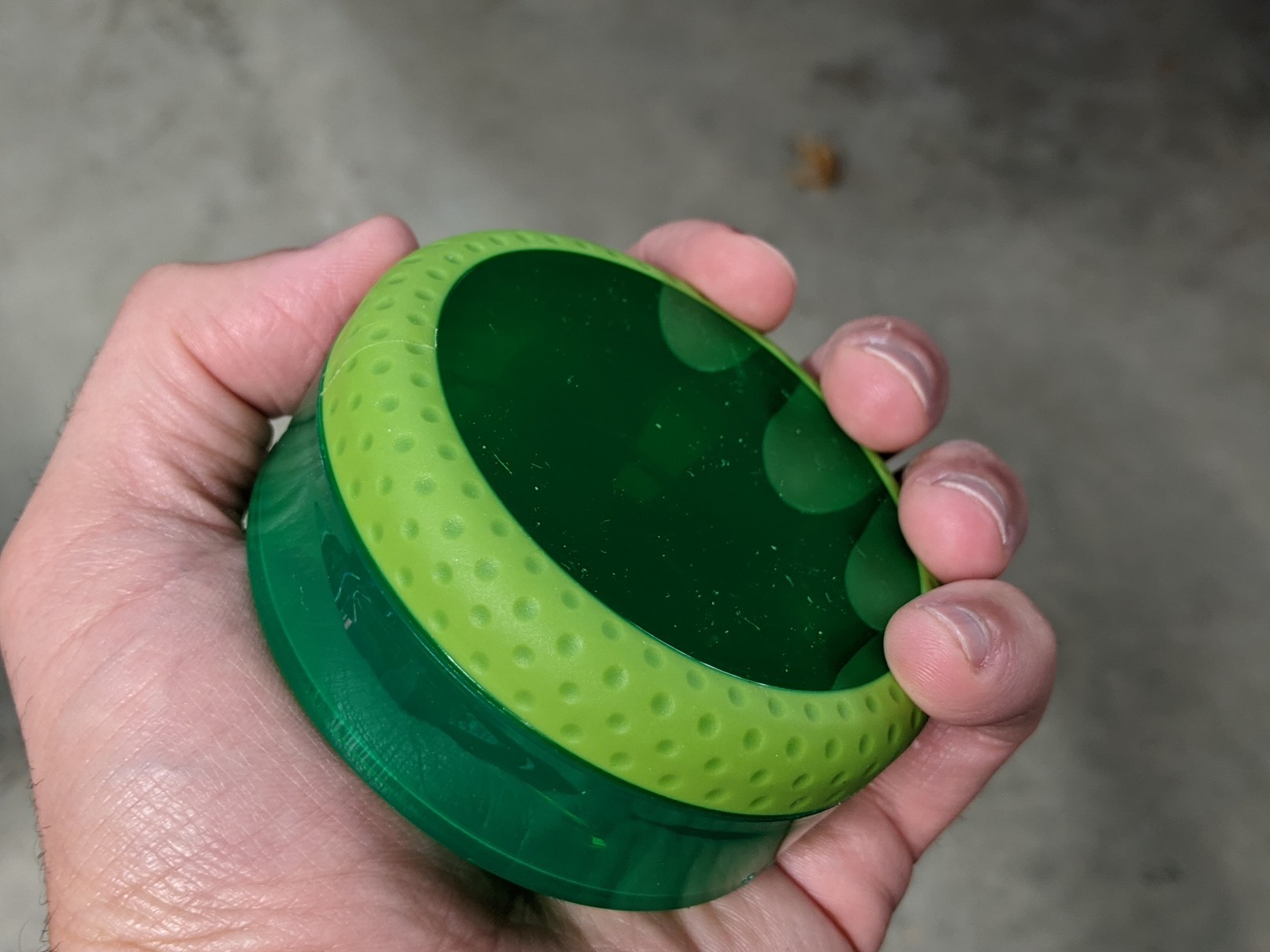
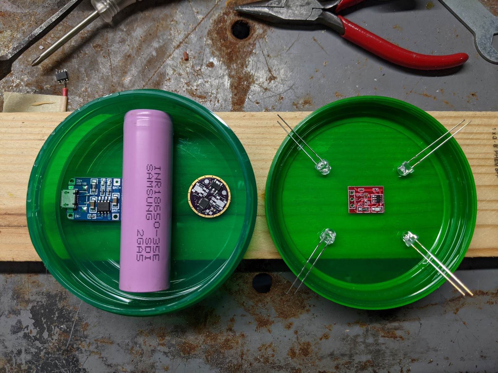
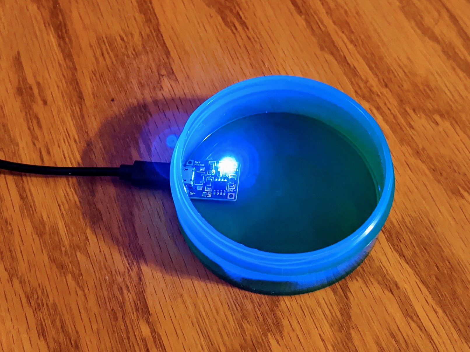
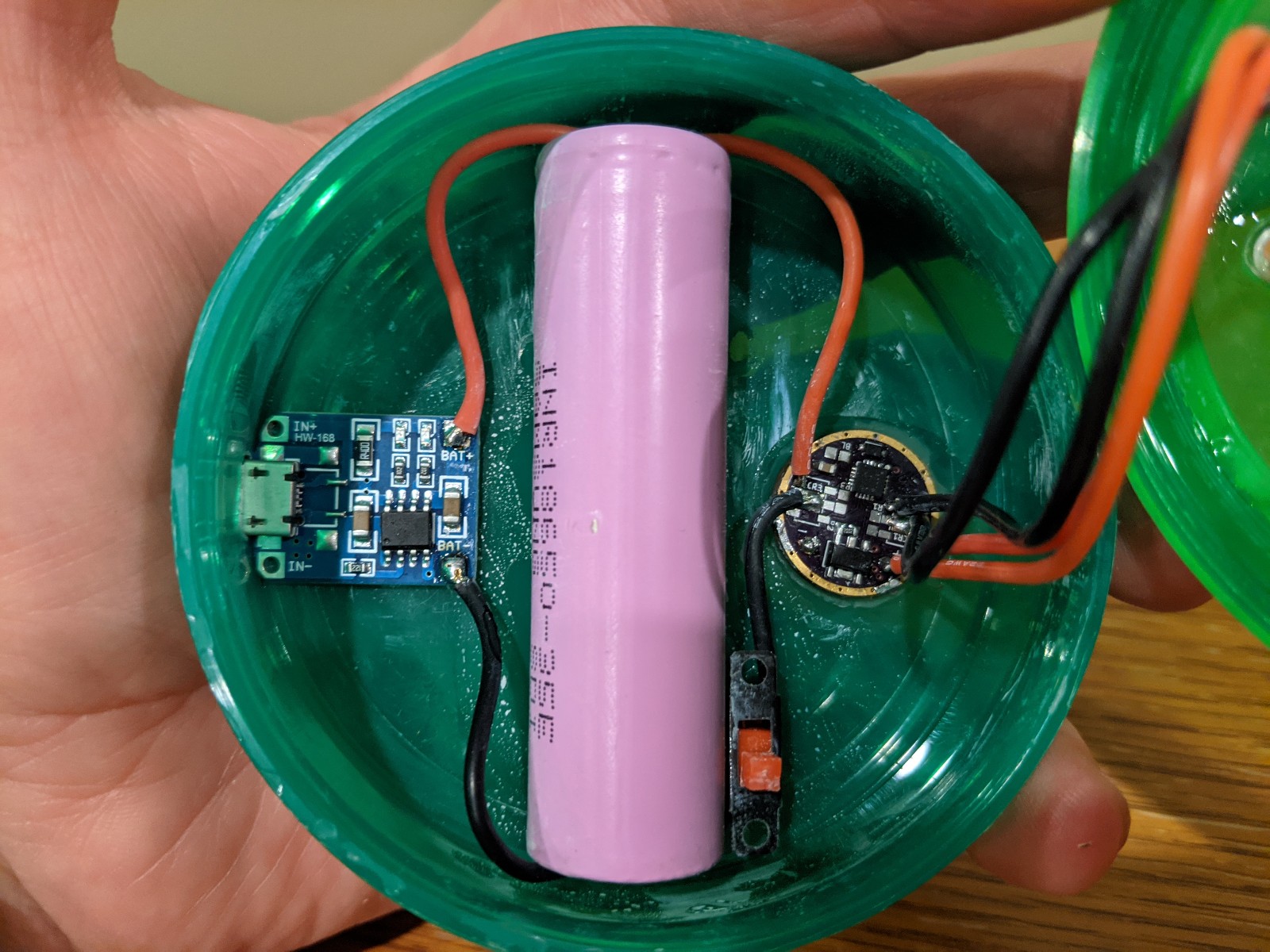
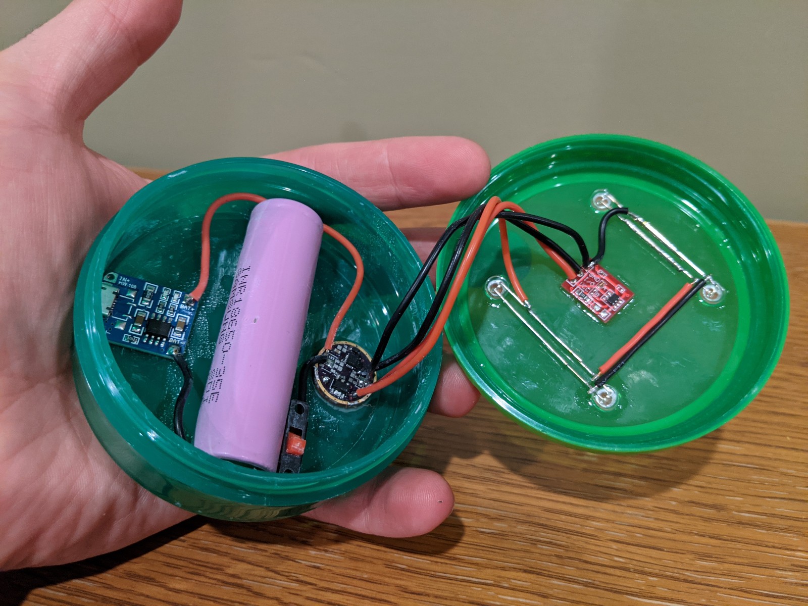
Just prepared the driver. I had to strip the components of an old test driver (that got fried) first before I could reuse the PCB. Truly pulling things out of the scrap pile for this one. Since Anduril has LVP, I won’t need the protected version of the TP4056 board, so I’m using a “regular” one. I also shorted Jumper A on the TTP223 to configure at as “Active Low” instead of the default “Active Ground”. With our e-switch drivers, all of them I’ve seen we switches as Active Low. The “host” is pictured as well.
Next up:
Filing the corners off the TP4056 board to fit the contours of the host
Create an Anduril config for this project and compile & flash it
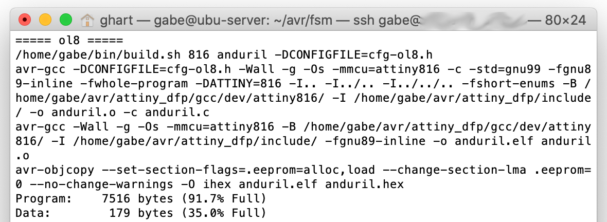
Cranking through this. TP4056 board is now (at least mostly) filed down. Anduril has been config’ed, compiled, and flashed. This was done in Linux, but I’ve also got Anduril for the 1-Series working just fine in Windows as well.
Up next:
Make openings in the body for the charging port and LEDs
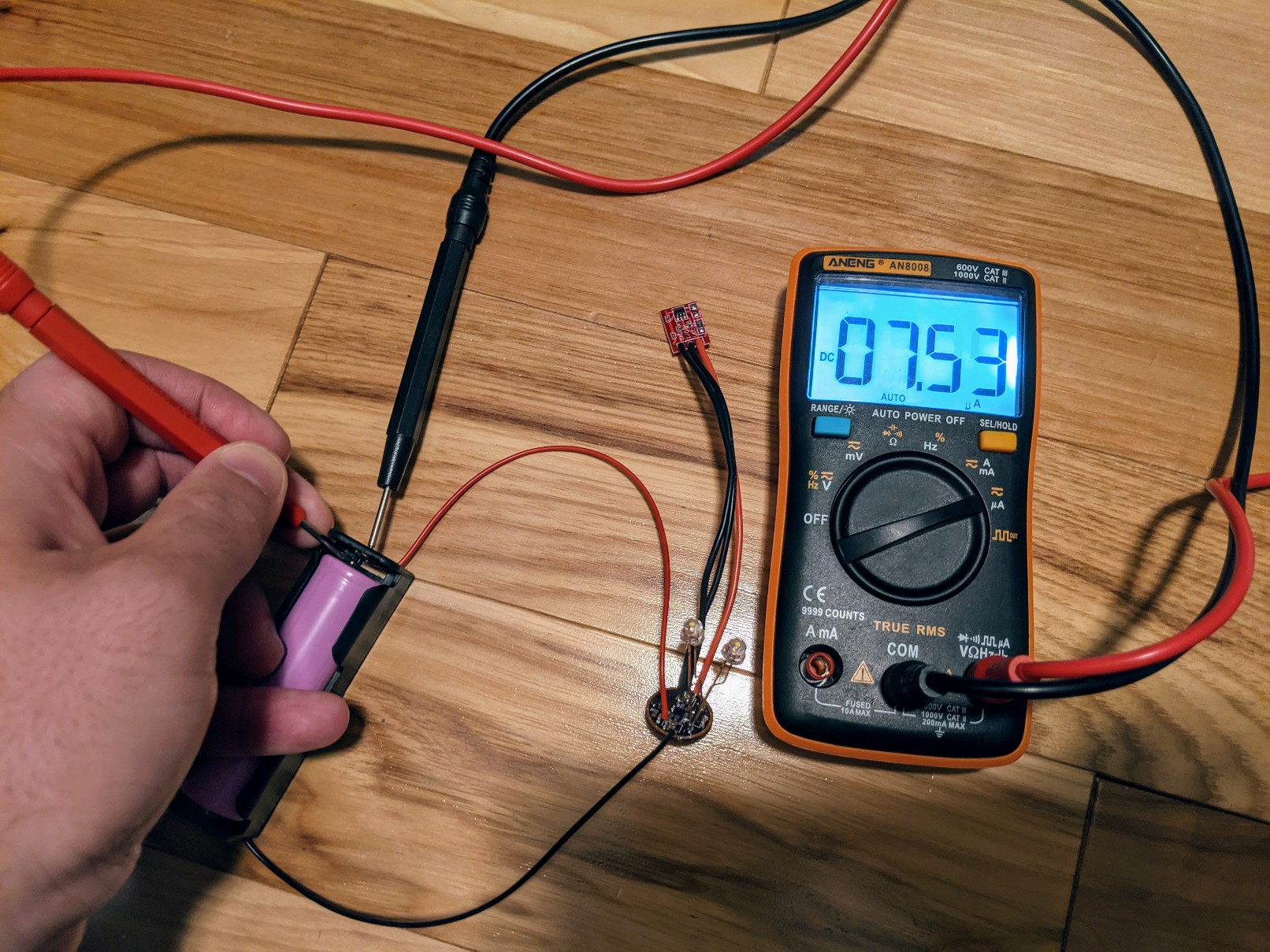
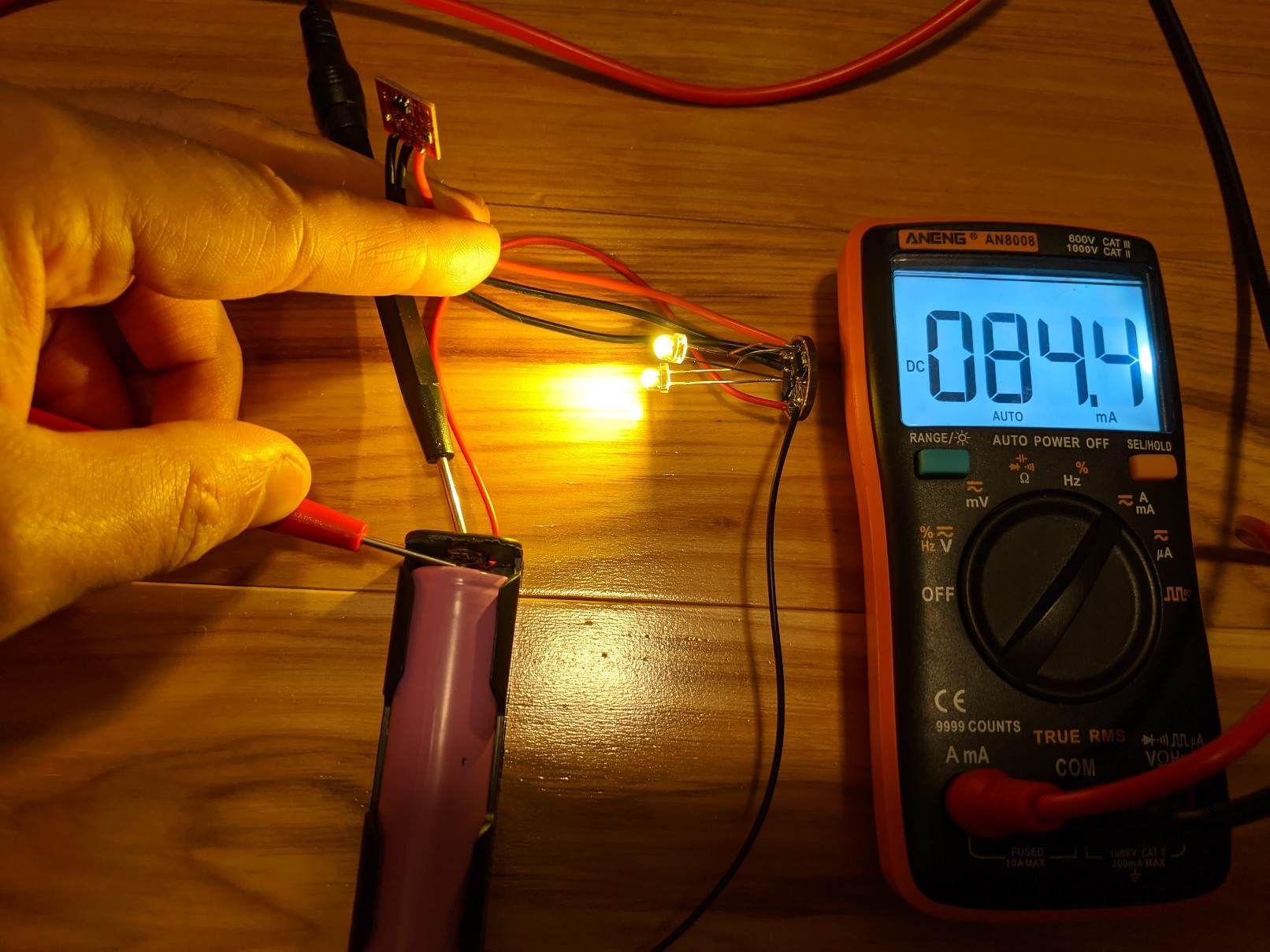
Current draw measured. In standby, the draw is a measly 7.5 uA. With LEDs at full brightness it’s 84 mA. With how I had the CN5710 set, I was figuring around 90 mA, so not too shabby.
Driver testing is complete. Anduril is fully functional! [WARNING - flashing lights!]
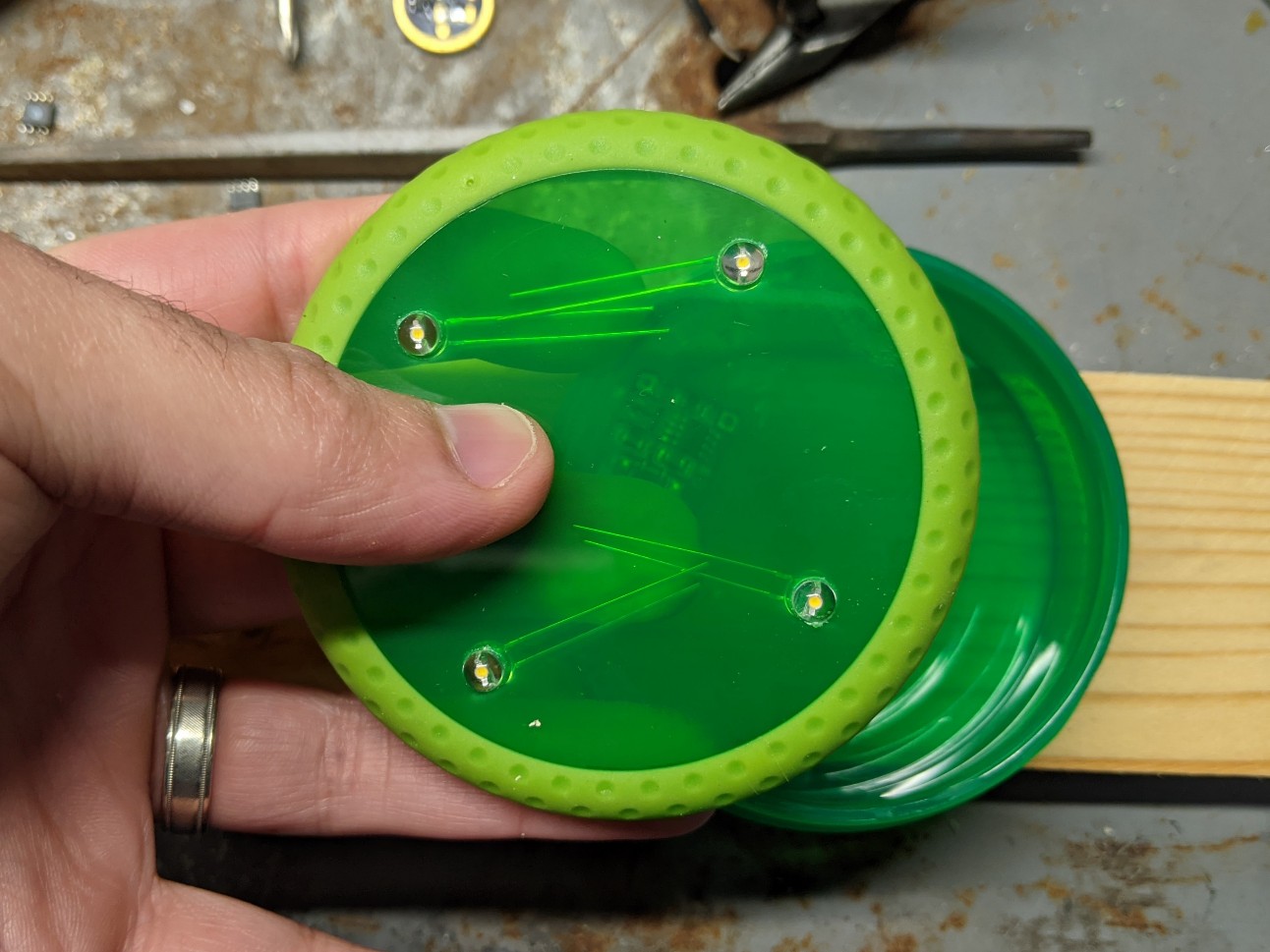
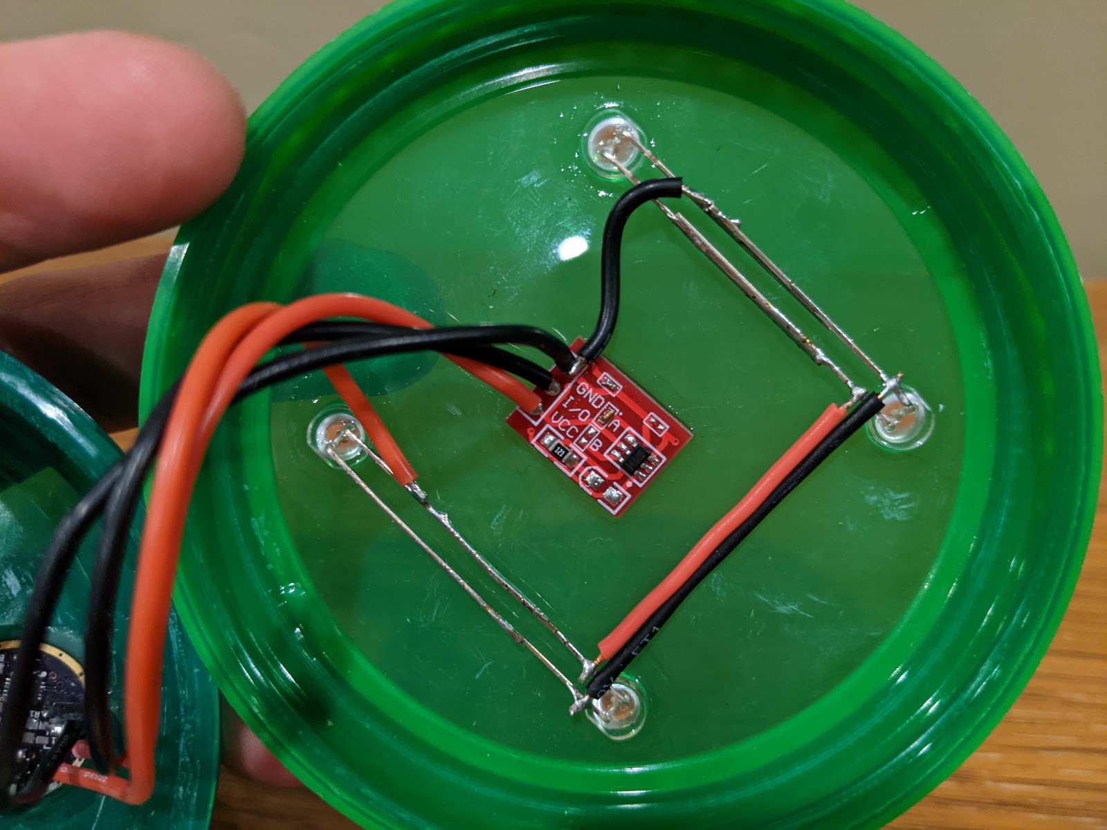
Small update, but it’s an update I guess. I drilled the holes for the LEDs and dry fitted them. Not quite sure what I’ll use to glue them in place… UV-cured glue? Hot melt glue? I’m out of clear epoxy. I’ve got JB weld but that would look unsightly. Probably just the UV glue I guess.
One of the more difficult things that I didn’t anticipate is that this kind of plastic doesn’t take glue very well. Hot glue was a no-go. Original Gorilla Glue fell right off. Gorilla Glue Super (CA) Glue Gel didn’t do any better. I ended up having some success with DAP RapidFuse.