What did you mod today?

Modded my Enogear/Fireflies AA Stainless Steel flashlight.
I picked the - already modded - 15mm driver with Bistro HD OTSM that I had in my Tool AA 2.0 Panda White, had to shave it a little more to fit in the brass pill of the Enogear.

I also picked the Luxeon V2 3000K I had installed in that same flashlight and put it into a 10mm DTP MCPCB I got today from LHT store in AliExpress. Well, and then I picked the pebbled TIR and also replaced the original clear TIR of this light.

I am not using the driver retaining ring because the driver is thicker than the original one and the ring doesn’t screw in.

Result: TOP! I like it, it only misses a FC switch instead of a reverse clicky! Aside from that, the DTP MCPCB will handle the heat better than the alu one! The beam is a floody warm white, which I love!

Now…I just need to make it a lanyard :wink:

I modded mine with a FET only driver but wish I had a 15mm driver with a 7135 or some other regulation cause it’s too much. Where did you find a TIR for it?

I read about your experience on the flashlight thread and figured that it would be a risky move! But with a MCPCB and a different LED I guessed it wouldn’t be so hard on the light :wink:
This driver is from Lexel and it has indeed a 7135 chip on the top of the driver.

The TIR is from this store at AliExpress: Page Not Found - Aliexpress.com

I bought some a while ago and I’ve used (and still use) them in different lights! It has the same size as the original TIR :+1:

Man I looked for this so many times. I guess I overlooked that 17mm w/ holder = 15mm without holder :person_facepalming: - thanks.

Next up find me a copper XP PCB that’s 1mm thick :slight_smile: - I think the “massdrop” AAA’s have them and some special lumintops. Wonder if they will sell separate?

And then finally a 15mm driver with some sort of regulation, Lexel MIA so I guess you have a very unique build!

Ahah, measurements when considering the holders are somehow tricky :stuck_out_tongue: I never use them, just the optics! And these fit well in other lights too (DQG Slim TI, Sofirn SF10, SF14 V1, Tool AA…) :wink:

As for the PCB, check these, the ones I ordered: 5.94€ 5% OFF|KDLITKER 3535 10 DTP Kupfer MCPCB für Cree XP Serie/Nichia 219 Serie/3535 LEDs|Tragbare Beleuchtung Zubehör| - AliExpress
This is the Kaidomain store in AliExpress, as you’ll see for their other products :wink:

Yeah, unfortunately Lexel may not be well and did another pause here, so these drivers are not available now. I wanna order some myself, for other mods, but I am not sure when will it be possible!

Hope you can do a nice mod with you FET on driver and those MCPCBs :wink:

I have those and probably some from MTN too. I vaguely recall it created a bigger gap than I liked with the pill. Guess I just need to sand them even though I dread doing it. There was some good suggestions in the last pages on doing it however. Using a hard stainless 1mm washer with 10MM+ ID might be the quick and dirty way.

Hum, when you say the gap, you mean between the PCB edges and the borders of the pill?

This is how it looks in mine (nevermind the soldering :smiley: ) :

I won’t bother too much with that because the contact “forced” due to the pressure of the optic+gasket in the MCPCB will make it get in contact with the pill!
As for the pill in the head and tube, I have no gaps when putting it all together :wink: All fits well, no gaps or rattles :wink:

I have found during SP10S emitter swap that Sofirn mcpcb is the same size as those in Olight Warrior Mini but for 3535 emitters. And Barry doesn’t want to sell them

USB BC1.2 charger for Convoy S2+

Intro

I was looking for the ultimate low budget cycling lamp. Discussed with my cycling mates, what would be good to have in the lamp: long lifetime or fast chargeability was on the top of the list. And one of them said: long lifetime and fast chargeability (charging while lighting), because he is riding long distances! Challenge accepted and started my design. My choice for the host is Convoy S2+, because it’s price, quality and availability. But it is just at the diameter of the 18650 battery, so it can be good for any single cell flashlight.

Looked around for the charging solution, I found a new device from Maxim Integrated, the MAX77751, which is a tiny form factor, but clever and powerful USB BC1.2 charger with up to 3.15A. Solid.
Additionally, I have to find a place in the host, where all the electronics can be inserted. One of my design aspect was to keep the original lamp as intact as possible, which makes this harder. But managed to make a small compromise, as I found another key component, the Hirose CX90 USB type C connector.

Mechanical design

Two PCBs are designed.
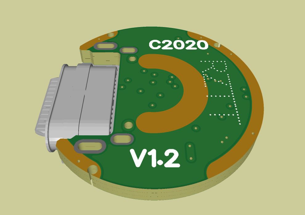
PCB A holds most of the components

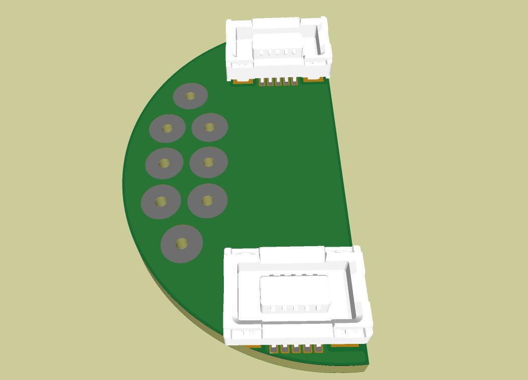
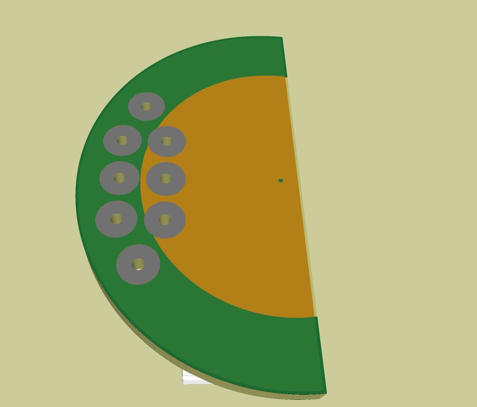
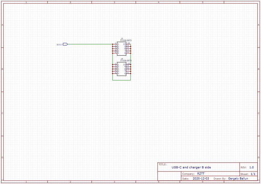
PCB B is designed to be the contact for the battery:

Manufacturing

Manufacturing was easier than you think. Just using cheap stencil, solderpaste, heatgun, steady hands and voila:

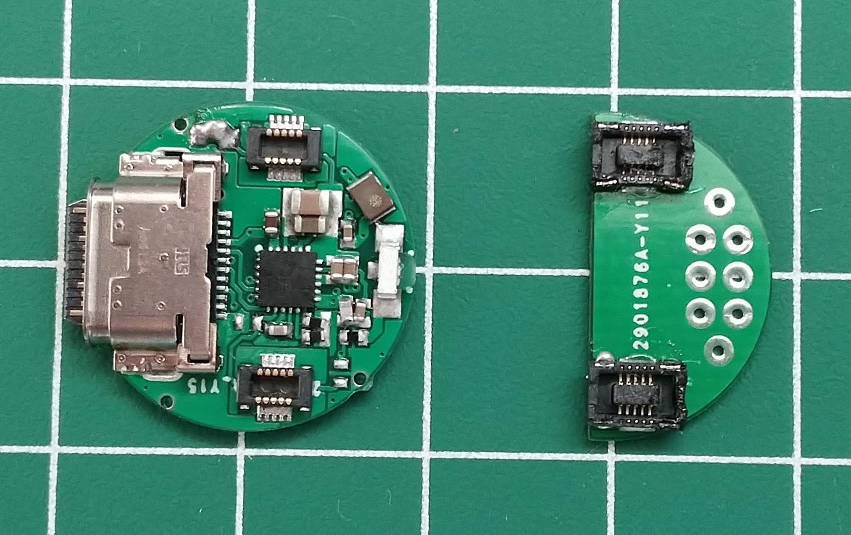
(I burned the Molex PCB connectors a bit on PCB B, but I can live with that :smiley: )

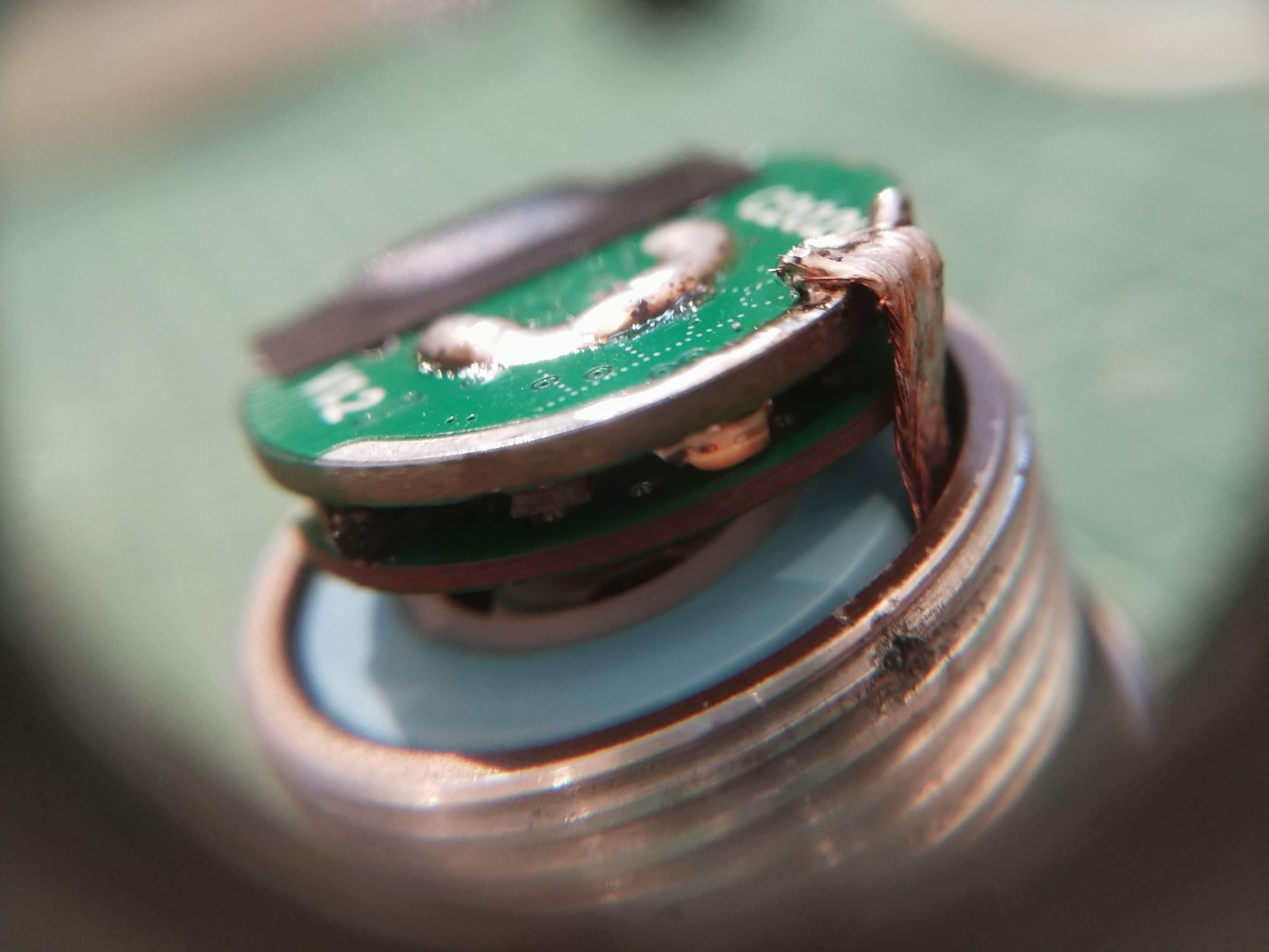
PCB B is sandwitched over PCB A to create a thick, COIN shape object:

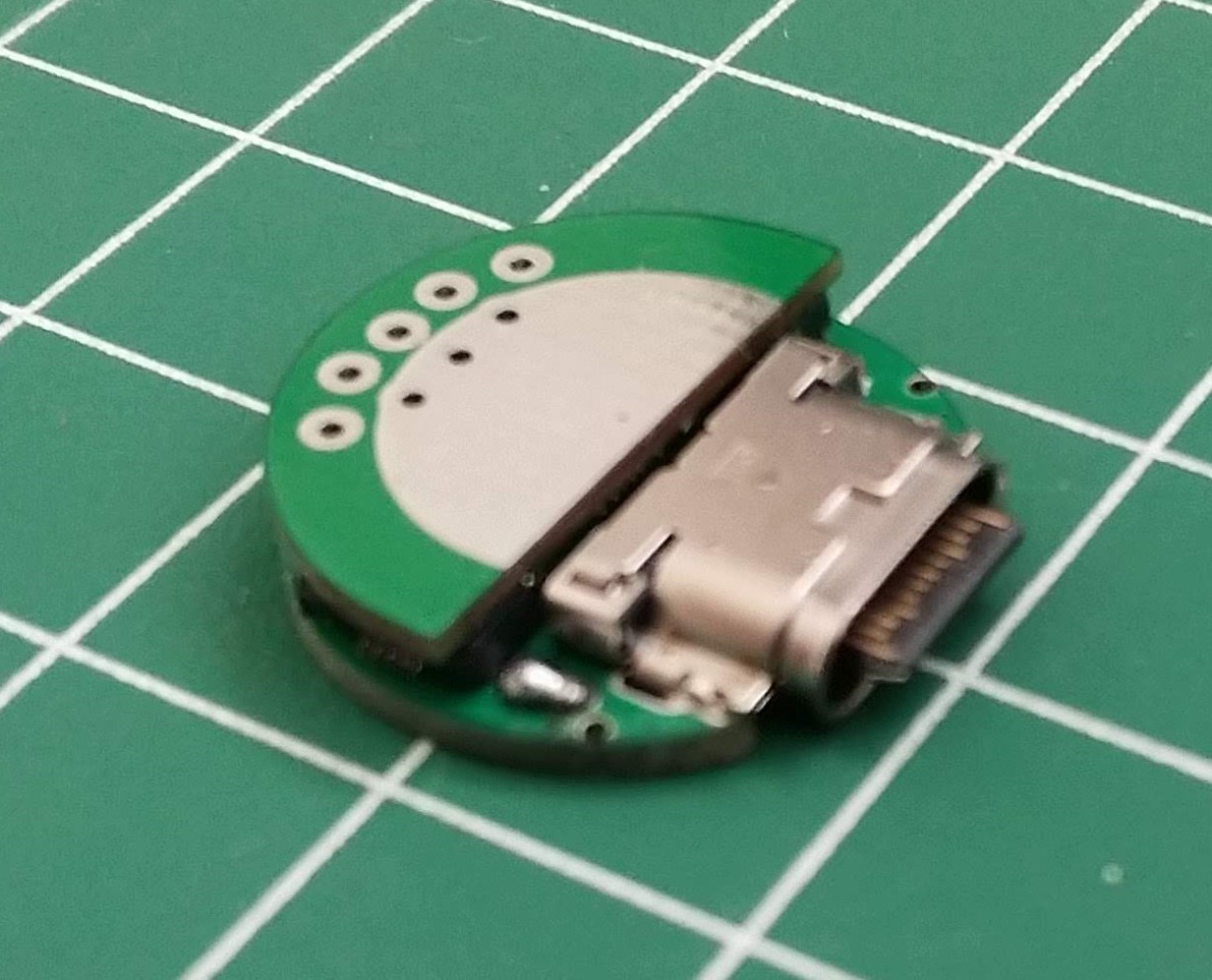
Added a thick solder layer to the contact surfaces for the battery (BATT+) and the driver spring (SYS, the C-shape exposed pad on the picture) connections. On the edge, a copper wick is soldered for GND:

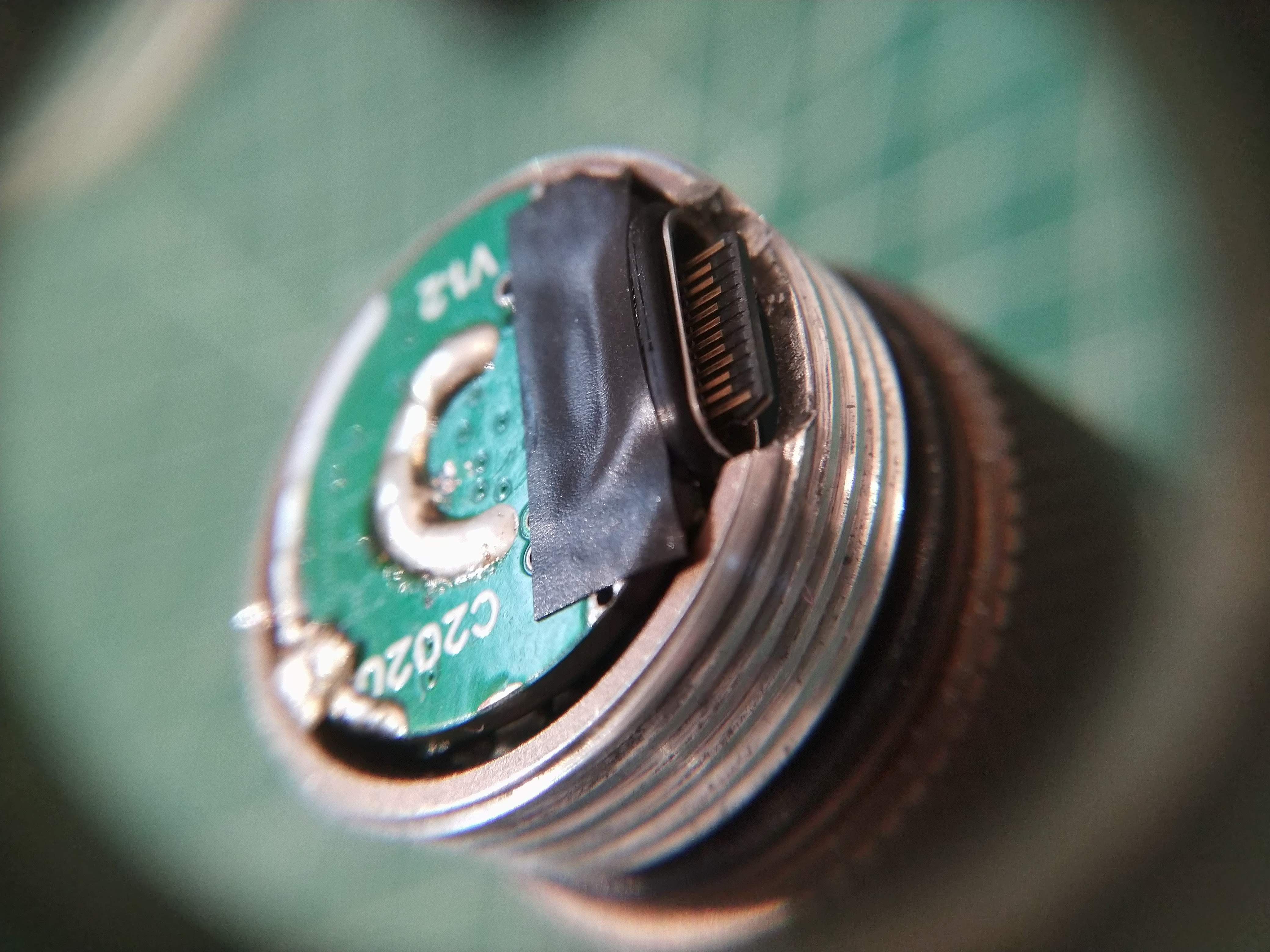
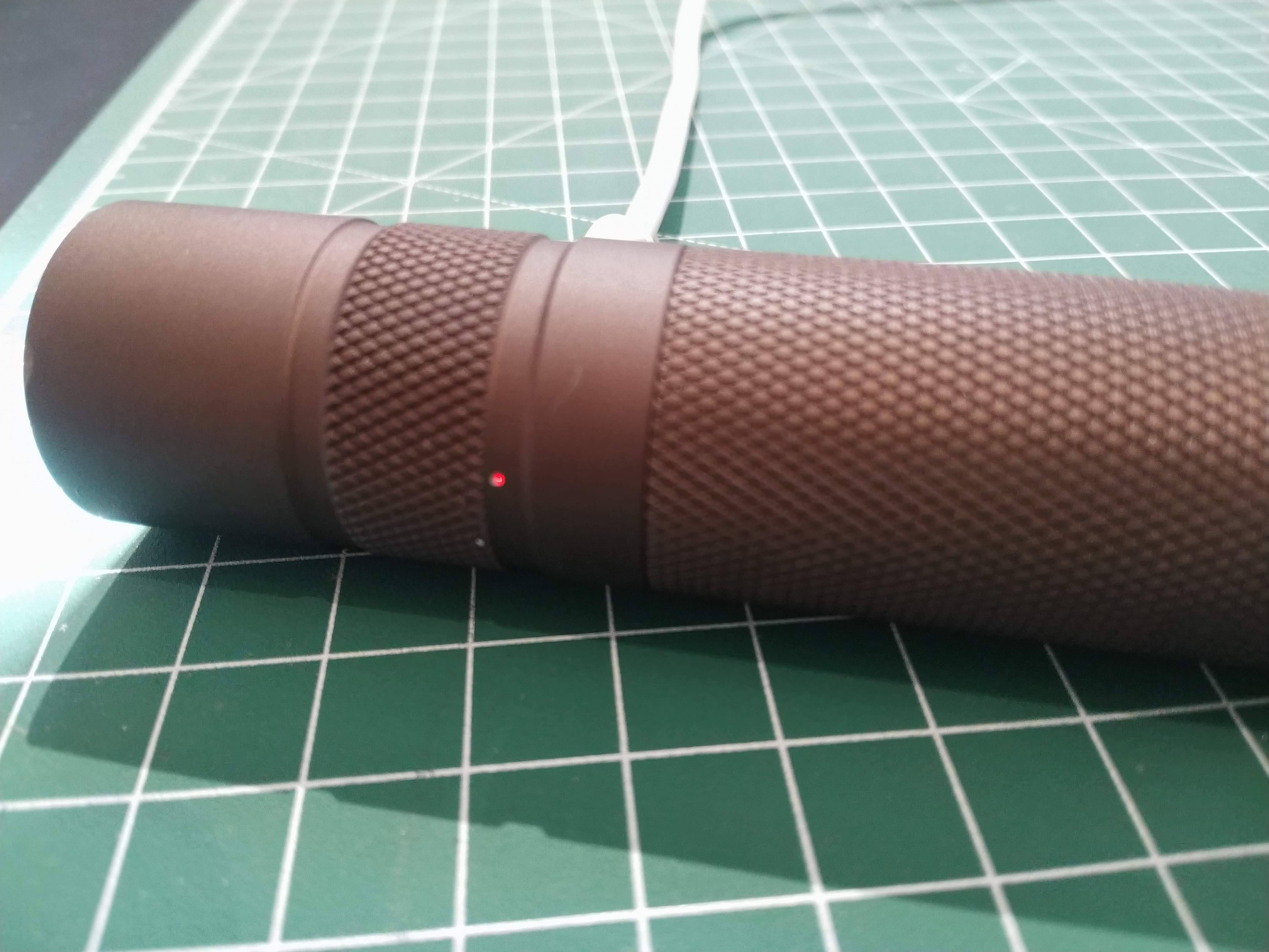
Note the cutout on the host tube. Electrical tape and rubber O-ring added to the USB type C connector.

Using drills and files and caliper for exact measurements a cutout on the top part of the lamp is made. The idea here is simple: every time you tight the thread of the tube and the head, their position is the same. First I made the cutout on the tube, relative to the Convoy logo. Then I projected this position to the outer side of the head and drilled and filed the oval shape object:

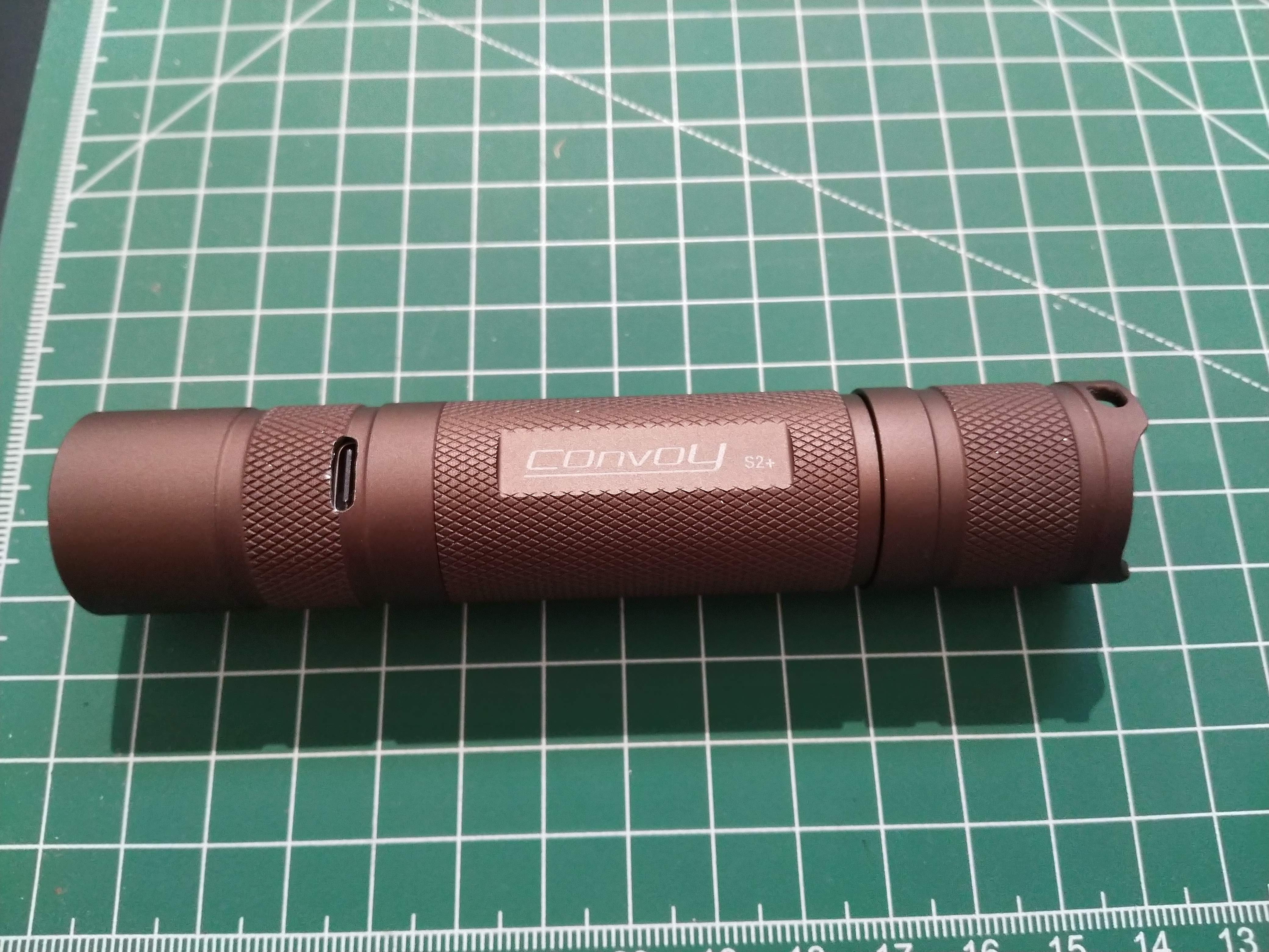
Here, you can see during charging. The small red/green dot is the indicator, shining through a tiny hole.

Engineering notes for the mechanical parts:

  • You have to pair the head and the tube, because of different item has different thread start position, making the alignment of the U-cutout of the tube and the oval cutout of the head wrong.
  • It is not water resistant. However, the Hirose connector has O-ring and watertight the mounting surface is not flat, but cylindrical there, having a small gap. The hole for the LED can be made watertight.

Electrical design

The schematic is based on the Maxim datasheet:

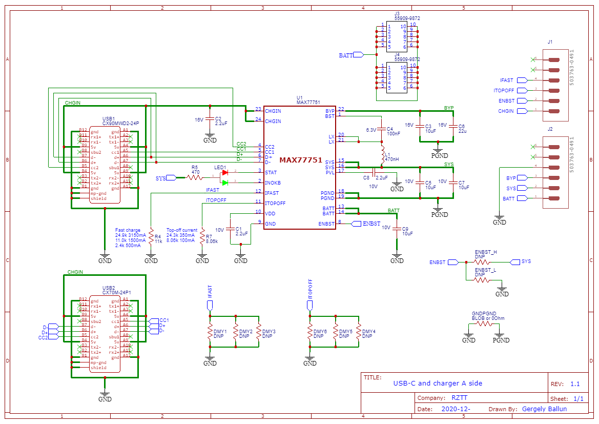
Straighforward design, however I have to add some engineering notes here:

  • The maximum current is limited to 1500mA by R4. I don’t want to kill the battery, but at the same time, I have to provide some juice for the lamp. As you can get max. 3.15A from the source, the remaining ~1,65A should be enough for that.
  • The topoff current is set according to the battery datasheet. Around 200mA we are OK in my case
  • Your charger will close the GND and SYS as you pluh the USB connector. Or you will close by your switch on the lamp before and light up. In both case, your driver will be activated, while you are charging. Since I want to keep the rest of the lamp intact (incl. whatever driver you use), I have to use this compromise. I just simply use a low power hungry mode (moonlight) during charging. On the other side, If your lamp is in a power hungry mode, the charging do not turn on. Other negative effect is, that during charging, you cannot control your lamp, since you cannot interrupt the GND line.
  • One mistake in the design: I used red for status, however, green would be more logical.
  • Important: if your PCB manufacturer cannot make buried vias, doublecheck their position, not to interfere with the SYS expode pad. That’s why I have v1.2 :person_facepalming:
  • The Molex PCB connectors are a bit overkill here. You can find cheaper and easier solutions

And one for PCB B:

There are some additional components on the schematic, because an evaluation board is made for exact measurements and for testing other USB connectors. They are marked with DNP (do not place) on the schematic:

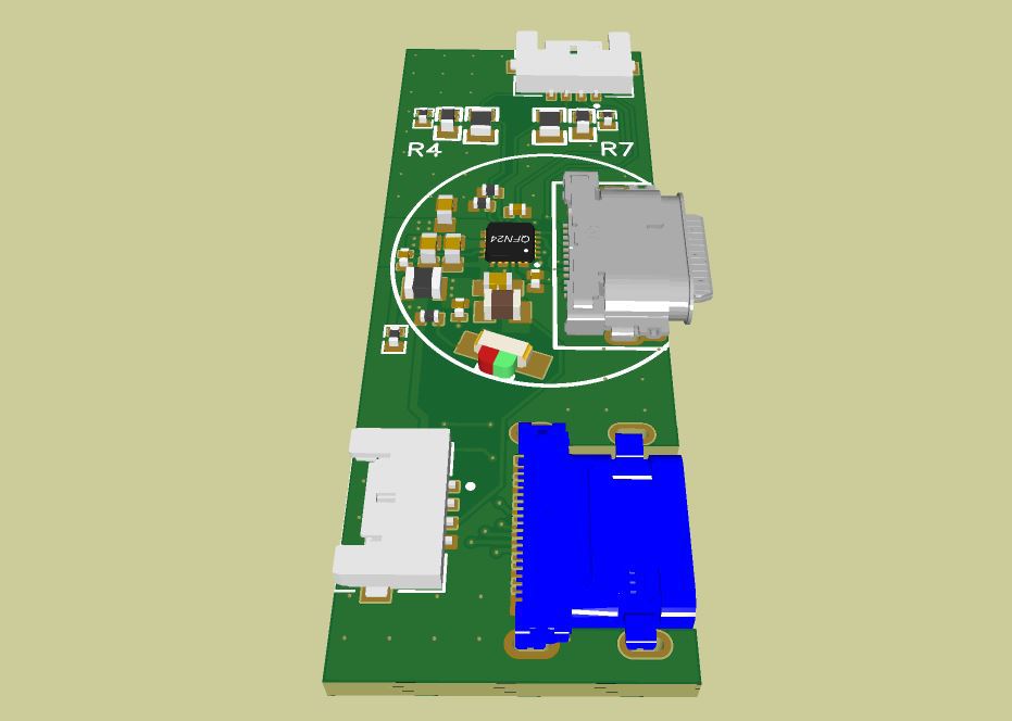
I used EasyEDA for designing, JLCPCB for PCB and stencil manufacturing. Here are the sources for v1.3 (other connector, swapped LED), feel free to use them and enjoy.

EASYEDA files

^ OMG how’s that for a first post :open_mouth: Ubercool Ger

OMG!

:open_mouth:
Wow. Just WOW.

Thanks.

Awesome!

My 2nd Enogear light with sw4500 219b was not working well since i got it and ended up on the shelf. I bought a couple of the new announced Reylight drivers, which should fit, hopefully it will work out pretty nice!

I will let you guys know the results when the parts arrive

Thrunite Ti3 mod to High CRI

WOW Ger, a really astonishing first post!!!

Received some Pebbled TiR, 25 degrees, thanks to a suggestion from moderator007

I removed the TiR from its housing, and replaced the centering ring and reflector on the Thrunite Ti3. It fits perfectly, still waterproof… whats not to love? :slight_smile:

Nice! Beaded TIRs are my favorite for tint consistency across the beam.
Do these fit with the original glass window in place? Which angle is your favorite?

yes, the glass is still in place

Ive only tried the 25 degree pebbled TiR so far, I dont think I would want it wider.

I agree pebble is ideal for tint mixing.

Pebble TiR makes a beam with similar diffused brightness gradient as a mule.
Brighter in the middle, diffusing towards the perimeter

Floody is Fun at the close range and low brightness level of these little AAA lights :slight_smile:

different beams for different applications
zoomie, reflector, tir:

+1.
Ger, you know how to make impression. :+1: