Nice mod! An attiny412 would fit perfectly with that pin layout (which is what the PIC12 chips also use). But attiny412 is a new 1-Series chip with a different programming style.
Bourbon Guy… Thanks!! ![]()
I saw that but I don’t have the skills necessary to configure old firmware for it, and I didn’t see any examples for clicky firmware.
It won’t help at this point, but I’ll try to get some posted this week. I just flashed a clicky driver with a customized Star Offtime.
Alright last one. I don’t want to clutter up the thread with basic stuff like this.
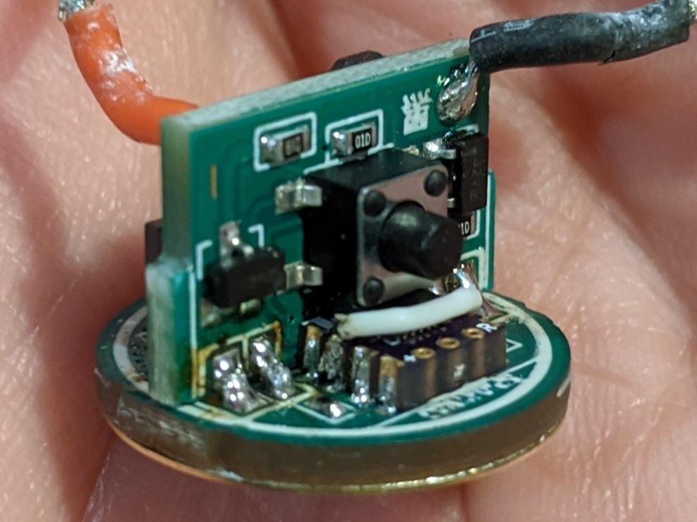
Yesterday’s successful result got me thinking about mcu swapping the stock Tool AA 2.0 driver so I could have a lower low mode and no mode memory while still keeping 14500 compatibility. That ticks all of my boxes and I prefer the Tool AA to the convoy T2.
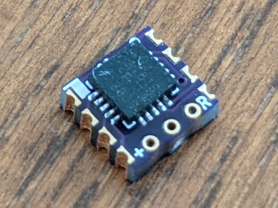
I really don’t understand how this driver works but I identified the VCC, ground, and PWM pins just like the convoy driver. Pin 1, the question mark on the top left, is coming from the small fet to the left of it. No idea what it does and I didn’t use it. The question mark pin on the bottom right runs through the 100k ohm resistors below the mcu and connects to the leg of the main fet. Also no idea what it’s used for.
The mcu pad spacing is tight and I didn’t really have wire small enough so I only connected to the pads for VCC. There are 2 common pads next to each other so it’s not as difficult. For ground there is a convenient spot marked G on the other end of the board. For PWM I connected directly to the fet. I used a attiny25 with minidrv 3 modes no memory for this one, and I swapped the stocki xpl for a nichia 219B. I measured a NIMH immediately after the light shut off on high and the cell was just over 1 volt.


I really enjoyed reading about your mods, please don’t stop posting. :+1:
Not clutter at all. AA Boost drivers are really lacking so it’s great to see what people can come up with.
Here’s a couple things I threw together for using the attiny412 with a clicky driver. Honestly, I feel like the 1-Series is a lot easier to code for - the register names are more like English names instead of 4-5 character abbreviations.
- Very basic testing firmware that shows setting up PWM and using the ADC to check an off-time capacitor (OTC). Link
- Cobbled-together (but tested and working) firmware with bits off Star (JohnnyC), RampingIOS (Tom E), and some custom stuff (myself) that can be setup with or without memory. It has voltage monitoring and a basic temperature control algorithm. Link
Note… I had to use an OTC instead of our neat “noinit” trick because the 1-Series memory doesn’t seem to decay for upwards of 45 minutes. That’s way too long to be useful for “short press” detection.
Awesome. I’ll be playing around with this soon. Thank you very much.
Anduril2 on a Sofirn SP10S? Sure, why not! Made a PIC12 to AttinyX16 adapter board.
Note: for the voltage divider, I accidentally picked a pin on ADC1 instead of ADC0. Rather than hacking Anduril to switch between the two ADC’s (temperature sensor is on ADC0), I just ran an airwire. Not great, but it works.
I currently have a klarus mi7 ti pulled apart and I’ve been pondering how I’m going to proceed. I’d love some details.
Did these lights have a voltage dividing network for LVP stock and you just utilized that?
Does the boost circuit run completely independently from the tiny? If it’s always on have you measured quiescent current?
Any idea what boost controller is used?
Seriously epic stuff. Well done.
gchart, That awesome!
Thanks guys!
@Bourbon Guy: I can get you more details later, but it already had a voltage divider network. I think it’s a 2-stage boost. A small one is dedicated to powering the MCU and a second larger one for driving the LED. I haven’t measured the quiescent current yet but I will when I get the final config settings dialed in.
Great work gchart. I know you have spent a lot of time on this and thanks for sharing.
So is this the first modified diver to work with a AA and Anduril?
To my knowledge, yes. I did have to add in extra code to handle the dual voltages.
.
You guys are the next level of flashlight modders. ![]() Amazing accomplishment. :+1:
Amazing accomplishment. :+1:
There are guys here who can follow in your footsteps, so you are raising the level of flashlight options and fun.
I love watching your modifications ‘gchart’ , Thank You for sharing your hard work :+1:
.
gchart - this is remarkable! If you have time, I think we need to go over this in detail in the BLF SP10S thread.
Just got a Nitecore TINI 2, swapped out the stock emitters for 2x 4000k LH351D’s. Looks excellent, very happy with it now.

FW3A w/ 1x Osram Red Flat (as secondary) and 2x Samsung LH351D (as primary) flashed with Anduril 2
Not sure what to think of this one. I don’t like the Mountain PCB with the XQ-E pads for secondary because it makes a hideous looking rorschach test beam (I think it’s a bat). This is definitely better. The Osram beam is pretty even, albeit a little square up close. This is with 10511. The white LH351D is fine with only two, looks round except for the usual spikey edges all triples have. Also wanted to give Anduril 2 a try since I had to reflash this thing anyways, two birds one stone. May try XP-E2 far red to see what a domed beam looks like if I ever take it apart again.
Hideous test setup. 18650 battery holder, separate e switch, alligator clips, etc.

1x7135 trace cut and negative secondary wire (in orange):

MCPCB mods. 2x traces cut and LEDs reversed to create a second negative pad for Osram and common positive for everything else. (keep in mind this will be different for ALL other boards besides LED4Power)

Always clean up

Wired

Hex file with new ramp table and latest (as of today) Anduril 2: google drive link

special thanks to staticx57(?)
Nice work on this one!