<< Lume X1: 40W Single-Cell Boost Driver with Anduril2 and UDR >>

Very nice, I am also designing a boost driver based on the TPS61288, it’s similar to the MP3431 but with lower but still largerly sufficient 15A switching current, and a smaller package which is good for our small boards.

It’s taking quite a bit of time for me because I need to learn basically everything about electrical and board design.

Anyway I’m curious how you implemented ultra low level. What I came up with is to switch between two sense resistors with a NMOSFET, a low value one for the higher range, and a higher value one for the lower range, achieving a very large range.

Could you detail how you implemented it ?

Edit : where did you buy the TPS61288, I only see it on Mouser and they will have it only at the end of March.

I’ve been waiting for years for a driver like this and I’m extremely pleased to see it.
What’s the diameter?

ADDED: also, any chance of it being mass produced? :wink:
EDIT2: I see XAL7020 on the pics but you mention a ~3 mm inductor. Could you clarify?

Markings are the same on a 7020 or 7030 for 2.2μH

Ah, so the number is inductance. Thanks for the clarification.

EDIT: Looking at the pictures I think that actually it may be a 6030 sized inductor. XGL6030?

Saturation current for XGL6030 2.2μH seems to be too low though.

Wow :+1: :+1: :+1: :+1: :+1:

Good lord, you continue to astound with your builds loneoceans. I’m most impressed that you managed to get such a low output using a current regulation scheme without any kind of circuit noise making it to the output. All my experiments in current-controlled low outputs have resulted in candlelight flickers as the switching noise makes it to the output. You must have a rock-solid control circuit going there - my hat’s off to you!

I also thinked these days that new TPS61288 is good candidate for future boost drivers and loneoceans just released today that new driver. Also is very interesting what type of feedback is used for measurement of such low currents. It is need to be very precise. I think is used very precise current sense amplifier and not just single low offset zero-drift opamp like in lume1 and GXB drivers where is work more like just current comparator. Critical here is the feedback compensation for stability of system.

Digikey have it in stock. I assume he buy from them or is used maybe free samples from TI.

Ah indeed they do, unfortunately they don’t do the paperwork to clear customs so I would get large fees upon delivery. I guess I’ll have to wait for Mouser.

Ho - lee - sheet

!

Very nice write-up and cool build. :sunglasses:

Will it be possible to build this driver like the GXB172 with a parts list and the PCBs?

Well great. Beside GXB172 that i cannot build, there is another one grail driver I will just watch in posts like these... bummer

What would the maximum power be that this driver can handle?

You said that you’ve configured it for 40 watt max for a single cell. But if you have multiple cells in parallel you can increase its power.

The input peak current is limited to 15A with the TPS61288, for a maximum fully regulated output down to LVP it doesn’t matter how low the DCIR of the battery is since you set the output current so that you hit 15A Iin peak at Vin=2.8~3V, maybe a bit higher if you’re fine with a dip at the end. That should be arround 35~40W depending on the efficiency and the inductor value. Or if you’re fine with a basically unregulated turbo it can be a bit higher.

But if you’re going to have several cells in parallel in a bigger light then you would use a more powerfull controller/converter or put several in parallel (the MF01 uses 4 boost converters for example)

This is so nice! Where do I sign up for few?

I updated the first post with some additional photos and images, and more to come soon..

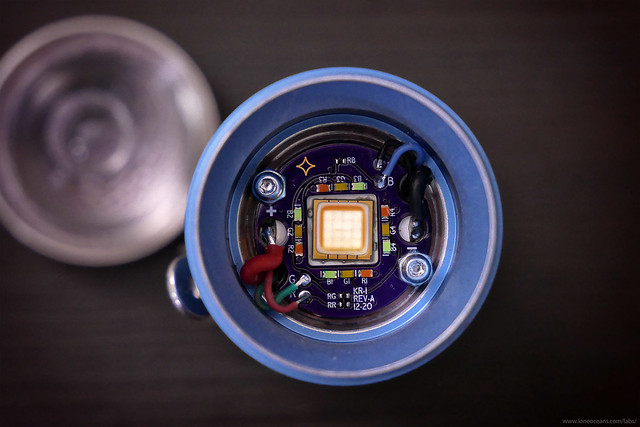
Above is a photo where you can admire the bare LED die construction.

Here's a comparison shot - what are they? Scroll to the first post to see :)

Thanks everyone for your interest and kind words.

For the converter, I purchased the TPS61288 from TI directly a few months since I built a development board for this project to fine tune the circuitry and to ensure everything works as well as possible before building a form-factor PCB. Though as pointed out, it's now out for sale on Digikey and other distributers soon. I also did a little component optimizing in terms of cost, and the BOM cost for this board is actually a good bit less than say the GXB172.

The general maximum input power is 40W if a good cell is used. One shouldn't simply look at the quoted maximum current input for the converter IC, since this maximum current depends on a lot of other factors as well such as inductor choice, switching frequency, load etc. I did some quick analysis and found it to be more a smidge more efficient across the range compared to the MP3231/29/32, and also because maybe I'm baised towards TI since I've used a lot of their PMICs and I do like their implementation. The idea of the Lume series of drivers is to create practical and reliable implementations, not to make lumen monsters, so I focused on efficiency & practicality instead of absolute maximum turbo modes.

For multiple cells in parallel, I always feel uncomfortable with consumer flashlights using inherently power dense cells in parallel or series without a BMS. It's generally OK in practice if the user uses three well matched, new, cells together, but problems quickly happen if the cells are not matched.

This driver is designed specifically for the use cases of today's high power, single, 18650, 26650 and 21700 cells. The maximum power handling capability is designed around this power source. If multiple cells are used in series or parallel, significantly more powerful drivers can be created; for example if a 4680 cell comes into consumer production, I could make something like a GXB100 for it. If multiple cells are used in series, then it makes sense to design a higher voltage buck regulator.

Agro, I'm using the Coilcraft XAL7030 inductor for this particular build, though a bigger inductor like the XAL7070, 8080, or 1060 would be better choices. This inductor choice is limited by the physical size of the driver cavity, and I reduced the maximum power output slightly for this particular build due to this reason. The 3mm value refers to the z-height of the inductor.

Speaking of which, just wanted to point out that the Lume X1 is not a particular driver, but a general design topology. I don't think this driver as-is is remotely suitable for most hobbyists to assemble at home unless you're comfortable with soldering QFN packages on a daily basis! It is also currently designed specifically for the KR1 host (25mm diameter), which is also non-ideal since the KR1 is a lousy host as-is, and I don't think most people would want to mill out their flashlight to fit a driver. Most likely, a new driver needs to be designed for a specific flashlight.

Perhaps if lots of people are interested, hopefully we can convince some manufacturer to pick it up for their light to create something special. Personally I'd like to see a compact, side E-switch, single emitter (or multiple in parallel) light made by Hank with the build quality and design he's known for (just a personal preference, no hard feelings to other manufacturers). They could offer two variants - one with the usual linear driver and 3V LEDs, and one with the Lume X1 driver and a 6/12V LED,.. but that's not for me to decide. :)

Good point - I can solder QFN on the daily but I'd really be unhappy doing it with the hobby-grade equipment I have at home...

Looks pretty cool. I’ve been wanting better resolution in low modes for quite a while. That ramp must look incredibly smooth. :slight_smile:

Have also wanted to get a KR1 at some point, since it’s almost as small as a D1 but has the throw of a D1S. The D1’s side switch makes more sense for a thrower though.

That’s jaw dropping, LO!

And about the attiny1616… I’ve been using it a lot lately and I’m working with some other’s on it. I’ve branched TK’s Anduril2 repo and merged in 1-Series support, just in case you’re interested in it for future builds. I also have a general 1-Series info thread here (not that you need any kind of help!)

Very impressive. And have you configured Anduril to ramp through this full range? How many steps?

I do indeed hope some manufacturer likes this well enough to work with you to bring it into production. Hank might be hesitant to move on from what is already a relatively new driver for him, and he seems to like the power handling of FET’s, but if he can find space for a taller driver, I think his lights would have just about achieved perfection.

I had not looked at the Ledil Olga before, but on seeing your picture of it, I realized the facets are angled. Looking up Ledil’s information on it, they indicate it is intended to minimize color artifacts when tint mixing.

An implication of this is if your center LED were small enough for the auxiliary LED’s to fit under the cavity in the optic, they may mix more cleanly than what we’re all used to for auxiliary LED’s.