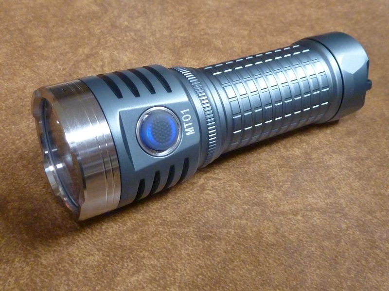
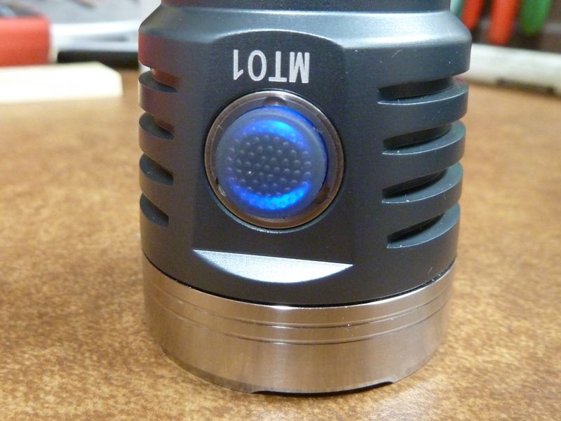
With the Astrolux EA01 out of stock, and the Mateminco MT01 offered at an excellent price on their Ali Store here ($36 for SST-40), I decided to order the MT01, exact same light as the Astrolux EA01. It arrived the other day, way ahead of the EA01 XHP50.2 I ordered earlier from BG. I was intrigued to see how the TIR style optic performed with these not-quite-made-for-throw LED's. But first, let's see what it's made of.
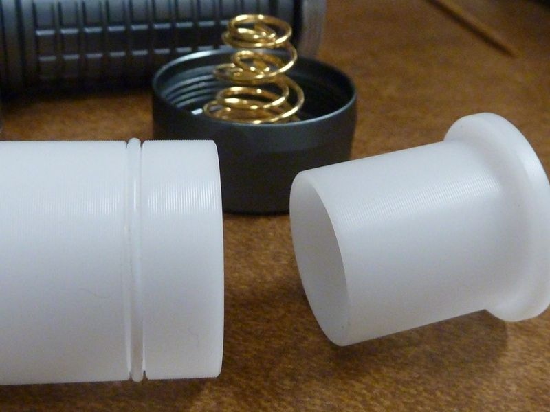
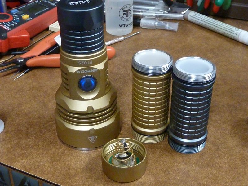
Here we can see the battery adapter - 26650 (no adapter), 21700 (just long tube), and 18650 (both tubes). With the o-ring , it's a nice snug fit.
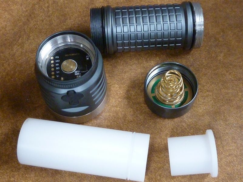
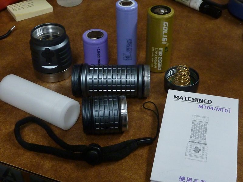
Here's the included pieces and sample of batteries that can be used:
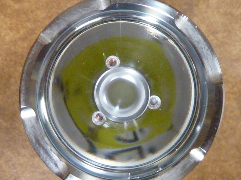
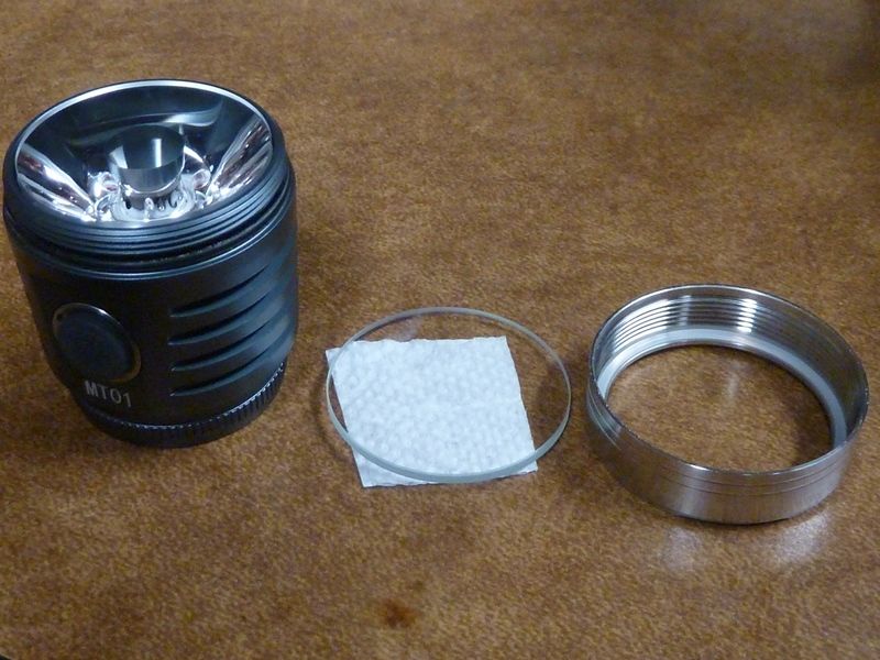
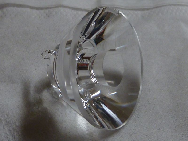
There is a glass lens, and appear to be untreated - can't notice any color reflection. The glass and TIR optic is in pristine condition:
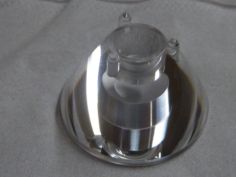
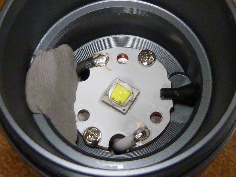
This is showing the 3 holes for the optic stems/legs in the 20 mm stock MCPCB. Also notice the silly putty/clay type substance covering the switch hole and switch wires. Guessing it's either to maskthe switch LED light from coming through, or to hold the wires in their place, or both. There appears to be enough thermal grease used, as can be seen oozing out into the 3 optic leg holes. At this point, I didn't remove the MCPCB yet:
Wish I had a "Mateminco" pogo pin flash adapter. Have not seen one that fits these lights yet on BLF. This driver is an exact match to the FT02S driver. Also, I like they used a driver retaining, also exactly the same as the FT02S:
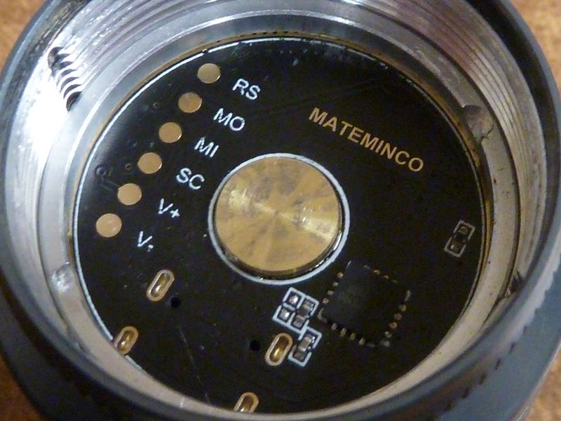
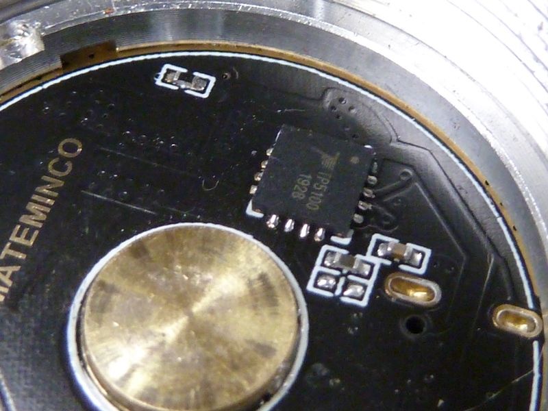
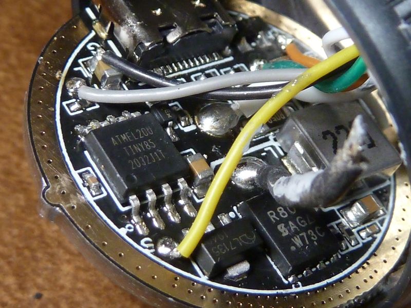
Classic FET+1 driver with the ATTiny85, SIR800DP FET (probably a good fake):
Short thick LED wires to keep the amps up:
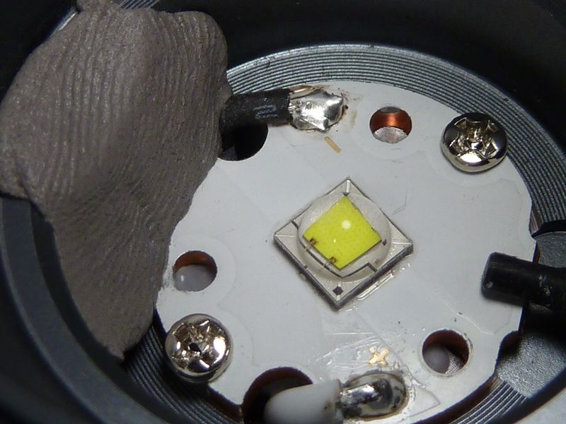
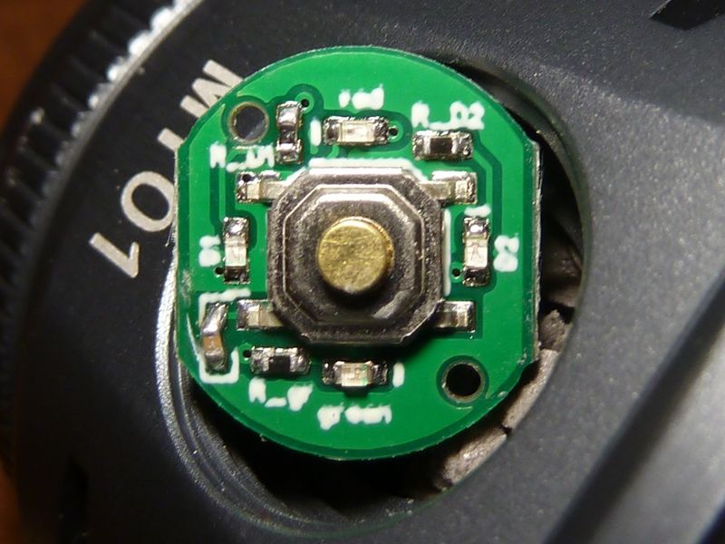
The labeling is actually that blurry - it's not the photo. Can't make out anything. Of the 4 LED's, 2 are blue (controlled by the Anduril), while the other 2 are either just RED or RED and GREEN possibly, controlled by the USB charging circuit (did not check USB charging):
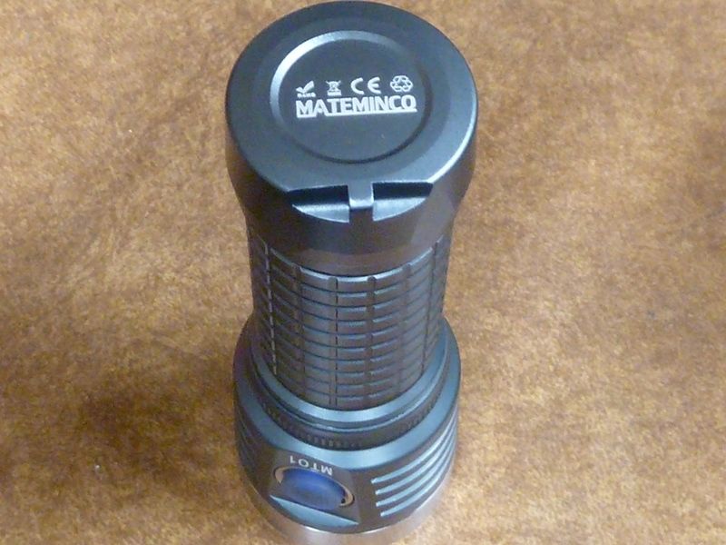
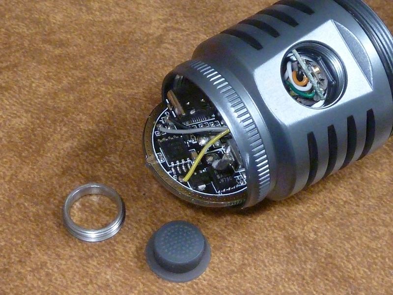
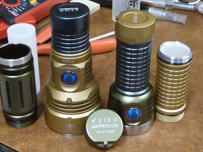
The battery tube and end cap of the FT02S are a 100% match with the MT01/EA01, while the MF01 Mini is a close match, so LEGO's pretty well:
Measurements:
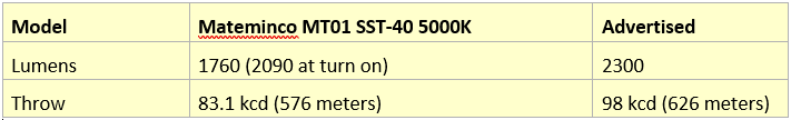
Notes:
- the light is all stock, using a 40T fully charged cell at 4.19V, 9.15 amps measured on a clamp meter, tailcap off
- lumens are calibrated numbers, taken in a DIY PVC light box, throw #'s are taken on a Extech LT45 meter at 5 meters
- the light was temperature calibrated and max temp adjusted high to run 30 secs without temp regulation droppage
