I recently did a led swap on a new in box xeno e03. Used the original mcpcb, took off the xpg (I think) and reflowed a sst40 5000k.
Weirdly, now the UI order is L-M-H… the UI on my other xeno E03 (and how it is on all from factory) is M-L-H.
I greatly prefer the new order, and I am wondering if anyone knows why or how this may have happened? Because I would try to replicate it with the rest of my lights.
Another note- on the original UI the difference between M and H is barely noticeable, but now it is spaced differently and much better. And most importantly, the L mode is also different and lower then original L mode, which is better.
Basically I accidentally made the UI really good and I have no idea what I did. I did have a hard time with the orientation of the new emitter (I put led on the mcpcb backward my first attempt) and had to reflow it twice. Does that matter?
Have you tried putting your new LED into your other Xeno E03? If it changes to L-M-H then it’s the LED, if not, then something else happened. Seems unlikely that an LED swap would impact the firmware.
If you had to desolder the driver first then you may have briged some jumper accidently to select the order when you soldered it back, but otherwise it’s impossible.
Changing the LED will not affect the mode order of the driver, and if the LED reflow went exactly according to plan then the process won’t affect the mode order either, but it’s possible that something was unintentionally done to the driver during the process which did affect the mode order, such as bridging a jumper as mentioned above.
And for reference, an SST40 has a different footprint to an XP-G (5050 for the SST40, 3535 for the XP-G), meaning they won’t fit on the same MCPCB Possibly means that the original LED was an XM-L?
Yes it is XM-L2, not xpg. My bad. I didn’t look it up before I posted the OP.
I have other xeno E03’s and they all have the same original M-L-H order, abd before I swapped the led so did the E03 in question. I used it for a week with the M L H UI, and now it is L M H.
The 14mm mcpcb is set into a brass pill, similar to pictures I have see online of the Reylight Pineapple and I’m sure many other 14500 lights.
When I reflowed the led I had problems with it working. I heated up the mcpcb twice to roatate the orientation, and once I even had the emitter perpendicular to the correct orientation and gave it power that way… yea I know… I’m an idiot…
So I don’t know if any of this “shocked” the system and changed the UI, I guess that’s why I am asking it here. The bridges thing sounds like it makes sense. Maybe when I resolderes the wires I made a connection from the mcpcb to the pill? I mean i doubt that changes anything, but maybe?
I’ll post a couple of pictures when I get to take it back apart.
I just reflowed another one of the brand new xeno’s and it did not change anything with the UI.
——>>>> I think I figured it out! Please read and confirm or tell me i’m crazy. thanks!
The UI must have changed because i reflowed the sst40 onto the xeno mcpcb “backwards”. here is my thought process -
I don’t know why, but this is the only difference i see between the two, and stems from my challenges when reflowing the first xeno LED.
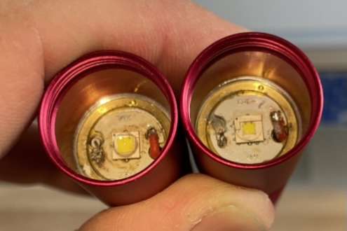
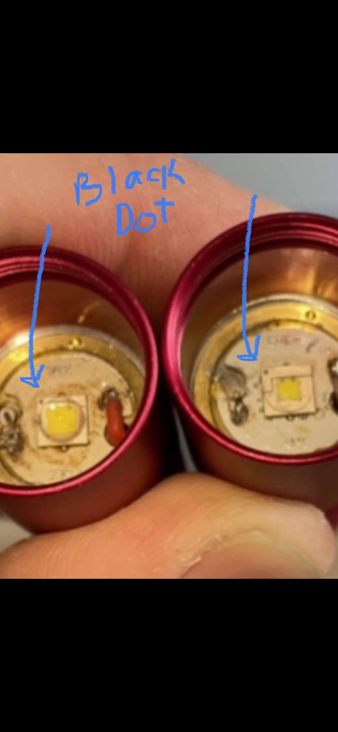
Below, notice the black dot on the corner of the sst40 emitter. On the left light it is on the side of the mcpcb that says “XML” (this is the one with the UI that changed and we cant figure out why) and on the right light it is on the side of the mcpcb that says “cree”. both of the mcpcb’s are identical, meaning that on both - the side of the mcpcb that says “cree” is the positive trace side, and the side of the mcpcb that says “xml” is the negative trace side.
Before i took today’s reflowed sst40 off of its original mcpcb (a noctigon 20mm), i noticed that the black dot on the corner of the emitter was on the positive trace of the original mcpcb, so when i reflowed it onto the 14mm xeno mcpcb i placed the black dot facing toward the positive trace (the “cree” side). The UI stayed the same. it did not change.
**I know you cannot really read the “cree” and “xml” but it is in fact there. these two emitters are opposite on the mcpcb’s. Does this make sense? i thought that the emitter wouldnt light up or it would be fried if you flowed it on opposite. or does this “black dot” mean nothing? and it is just randomly placed on a corner of the emitter?
Nevermind… that is not what changed the UI… I just replicated the above pictures of the changes UI emitter/mcpcb orientation with today’s reflow and the UI stayed original, no change.
Also, after I made that post I realized that I did put the led on the mcpcb opposite, but I also soldered it opposite therefore negating the fact that I put the emitter on incorrectly…
Yeah. you figured out after posting that although the boards are orientated differently the LEDs are both wired up the same. Round the other way it simply wouldn’t light, ‘LED’ stands for ‘Light Emitting Diode’ and a Diode only allows current to flow one way. (And these LEDs only allow it to flow once a threshhold voltage has been reached, below that voltage there would be no current flow in either direction.)
Is that a de-domed SST40 on the right or a sliced one? Looks like the dome has been completely removed.
The mode order is independent of the LED though, there’s no sensing going on. Genuinely can’t think what would cause the mode order to change unless the driver allowed for it to be changed somehow, but even then i can’t see how you would have implemented the change if you didn’t go near the driver, the only thing i can think is that a drop of solder or a piece of wire dropped down the hole for the cable onto the driver into exactly the right place, but the odds on that…
It’s clearly happened though and it could be very useful if you/we could figure out how, so i hope you/we do! Need to be looking at the driver rather than the LED though, i’m quite certain of that.
Thank you Marc E. yes this is all very intriguing, thank you for explaining how the driver and emitter function independently, it helps me understand more. Honestly the solder drop, i know it sounds like 1:1,000,000 odds, but i wouldn’t be surprised, just because this is so random. not only is the mode order different, and better, but the low is much lower and really nice. but the middle and high modes are the same and i didn’t lose any overall lumens. its just so weird, and good, but frustrating because i really want to do it to my other lights.
So, i completely agree, i need to look at this driver. i just don’t know how to get it out of a light like this, and i dont want to damage it. Do you have any suggestions for removing “safely”.
Thanks for the input. We all definitely need to figure this out
it looks like there is a brass retaining ring… see the little dimple holes? those are where you put the point of some snap ring pliers to unscrew… you can try tweezers… they might bend
however, I think you are chasing the wrong issue, here is why:
I have a maratac aaa that was MLH with a Nichia 219b, but after changing the LED to XP-E2 Red 660nm, it became LMH, and the mode spacing is not the same either. I believe this is due to differences in forward voltage of the LEDs
therefore
imo you have a mismatch with your new LED
if you go back to the original LED, I predict the original mode order will return
I suggest you NOT remove nor screw around with the driver,
unless reverting to the Original LED First, does not bring back the original mode sequence and spacing
The vf is a good point, the only thing is I reflowed another sst40 into a different xeno e03 this afternoon, and it did not have the same effect in changing the ui order. The emitter that I flowed into the e03 in question with the changed ui is also a sst40… this just makes no sense.,
I’m confused since Artiet59 did not swap out the LED like I suggested and instead reflowed another LED. In order to make sure it was the LED that made the difference, the same LED should be used in the other Xeno E03.