Last night left work late and the parking lot lights were out. We are out in the sticks here, at the fringes of the burbs, so it was pretty dark. My car was the only one left in the lot, far away, and couldn't even see it. I first tried the EDC18 in my pocket which is great for close range but useless to spot my car. So broke out the MT01 SST-40 and lit it up like daylight. It's quite impressive with a nice big spot and having a good working distance, and this was just on hi at top of the ramp, not turbo. It stayed cool enough the entire walk to the car. These are great lights for the money, but still room for improvements. Seems like the parasitic drain problem is specific to this EA01 model, and not rampant in Matemincos with my spot checking of what I got.
The list of issues I see/know of are:
excessive parasitic drain of various degree, varied unit by unit
sharp edges on the SS bezel, some worse than others
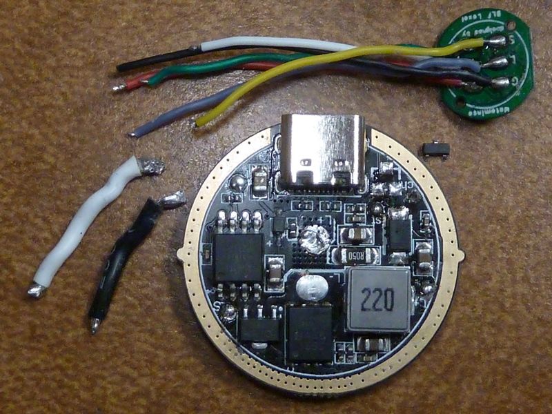
weird writing on the back of the copper MCPCB - why? Doesn't seem like a good idea on such a critical temp junction
where's the Anduril source code being used on this light? It should be publicly posted/accessible. Please!
still QC/QA issues piece by piece - are basic tests done on each light before shipped?
Everyone who has purchased the EA01 should check their standby current at the tail to see how wide spread this problem is. At least lock them out every time to be safe.
So you touch one lead to the battery tube and the other to battery - ? While light is off with lighted switch on low? Or lighted switch off? I’ll test mine if it is possible with my cheapy Amazon MM…
Yes, that’s right. The red probe needs to be plugged into the A mA socket to measure milliamps and the dial should be set to A mA also. You could try the micro amp setting (uA) but it probably will show OL unless you are lucky and got a low drain EA01.
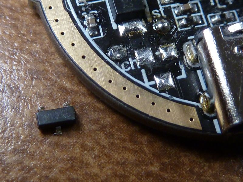
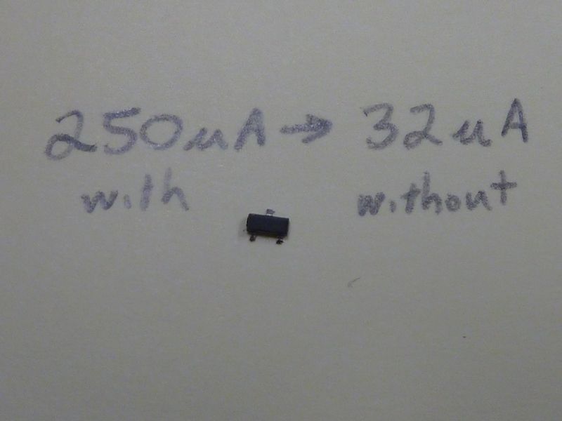
Found the leaky part. Removed a 3 legged IC, maybe a LDO, as part of the charging circuit and on the bench, the standby drain went down from 250 uA to 32 uA. This was on the EA01 that read 640 uA on standby with switch LED's off. It's probably the only cause but won't know for sure until it's fully assembled again, repeating the setup for the 640 uA reading. It was the only resistor outside of the standard LED driver circuitry I could find connected to ground (i.e. Batt -).
It bugs me enormously, I’m a great fan of USB-C charging within a light so I do not want to disable that. But with the casual way I handle flashlights (and so it should be, one should not have to think when using a flashlight) this light will continue to kill a battery every now and then.
And with 5mA parasitic drain (with or without the switch light on) I got the worst from the lot.
Haven't been able to get a good pic of it with the #'s:
Checked two caps in the driver circuit and one is 40 uF (C1) and other is 5 uF (C2). Our usual FET+1 design originated by DEL is to use a 10 uF primary (C1) of Batt+ to GND after the R5 4.7 ohm resistor, and an optional C2 of 0.1 uF between the V+ and V+ of the MCU. I'll have to re-check this - might be inaccurate to measure caps inline. Also know DEL wasn't too tight on specs for the cap values so these might be ok to use.
Yes - this one didn't work for me. I don't have the know-how to redesign the charging circuitry, so only option for me is to remove/disable it. Would be great if the 3 pin part could simply be replaced with a non-leaky one, but usually it's not that easy.
The three-legged component is an N-FET. 3416
I think it connects the charging circuit to the battery when you’re feeding the usb-c from the outside.
I’ll try to put resistance between Gate and Source in case it stays open and that’s what’s causing the problem.
Thanks for researching this! So the "Gate" is the pin marked "G"? Think the "D" pin was connected to GRND and another pin connected to Batt+ -- would that be the place to add a resistor? If so, what value do you think I should try?