Hello all,
First, wanted to drop a note to Mike C for sending me an email to notify me about his (excellent) work on his driver, which also brought me to this thread. I've been caught up with some extremely busy commitments recently which explains why I've been away for a while, and I've had to take a step back from BLF/Flashlight projecting. I'm not quite sure how long this will take (maybe several more weeks or a few months?).
Meanwhile, I'm really glad to see so many great talent and development on some new drivers. Keep up the great work thefreeman, MikeC, gchart, and everyone else working on this.
I haven't had the time to go through all the threads so here's some of my comments in no particular order, and I apologize in advance if it has already been discussed somewhere else.
The 1616 is a nice IC, especially since it comes in a 3x3mm package allowing it to fit onto small form factor PCBs. For my Lume X1 driver, I actually made an updated version earlier in the year with the 1616 after suggestion from gchart and his work in porting Anduril over for the 1616. I like how it only needs 3 pads for UPDI as well.
I agree with MikeC about the internal DAC part and I'm happy to see that he used it, which was what I also switched to for my 1616 Lume X1 design.
When moving from the 1634 to the 1616 on my version two Lume X1, I swapped the brightness control from PWM to use the internal DAC as a reference voltage setpoint for the switching regulator. The problem with PWM control was transient response from the PWM's low pass filter, and I found that using the internal DAC (as a reference voltage) allowed for faster transient brightness performance for effects, and when switching between ranges. I also found (just a guess) that the Zebralight uses a similar approach as well, using the internal DAC and internal op-amp of their PIC MCU for their switching designs.
For my original Lume X1 based on the 1634, I had to do some trickery in the code to adjust for it to make a visually smooth ramp with PWM control. I maintained the ramp at 150 levels since each level is based on Andruil's internal 'tick' and I didn't want to change too much of the code to change this 'tick' interval. I wrote a simple script to generate a ramp table for visually smooth ramping and it worked out really well as you can see in my original Lume X1 video.
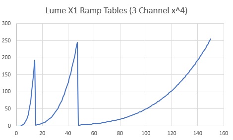
I tried different polynomials as well as exponentials but I found x^4 to work visually well.
For the 'Ultra-dynamic-range', it's exactly as thefreeman described, but instead of two, I used three different sense resistors each, each 2 orders of magnitude different. The key is to use a carefully chosen N-FET for the lowest sense resistor (highest current) since I take the R_ds_on of that Mosfet into consideration for the sensed current. Instead of focusing on the lowest R_ds_on, I picked one which is the most consistent at the driven gate voltage. I also played around with switching the reference voltages for the internal DAC to achieve more dynamic range too. Another note is that the DAC output is not quite rail-to-rail so you need to take into account for the lowest output voltage of internal DAC for the lower voltage ranges.
I removed the external temperature sensor since the 1616 seems to have a more accurate factory-calibrated internal sensor which the previous MCUs did not have to the same degree (though I can't find any manufacturer data of the exact accuracy tolerance). I'd also recommend ensuring the MCU has a good thermal path so the sensed temperature is accurate. Remember to disable the temperature re-write during Anduril's factory reset.
Due to the fact that the system now uses a higher current sense voltage, the other important aspect (especially since I'm hoping to design a driver that is economical to produce as well), is to use a less precise op-amp, saving a fair bit of BOM cost. I chose the much cheaper MCP6V66 with excellent results, but I suppose most other similar ones will work as well.
I got a few questions on compensation - compensation for the TPS61288 regulator itself should be fairly simple (the datasheet provides a good way to calculate it), but the op-amp compensation is a little more tricky if you're optimizing for lowest noise, EMI, and stability at all expected inputs and output loads. This compensation depends on the exact parameters of your circuit so it doesn't really make sense to port from design to design (and especially for op-amps - esp. the GBW and how it is set up internally since a lot of the precision op-amps are choppers) since it is also partially layout dependent; I'd encourage you all to play around with different values. I build dev boards for all my driver designs to help with this.
For the Lume X1, I chose a 'conservative' 40-ishW output since I wanted the driver to perform at its expected output across the entire battery range (as opposed to claiming that it was a 50-60W driver, but only with a fully charged cell at ideal conditions). I could increase this a little if I had full reign with the flashlight design as well to optimize for larger passive and magnetics, and flashlight power path.
Since then, I've managed to design one to fit an Amutorch E3 with 3S output configuration, and overall performance is really nice (main limitation being the inductor, and I've adjusted the output to be lower as a result to prevent inductor saturation)! thefreeman, your copper ring design looks great; it's a nice way to fit in a larger inductor (I had to use a flatter, lower power one for the E3).
Finally, I don't have any real thoughts between the MP and TPS part, both seem to be decent, but I do prefer the TI part for its lower Rdson FETs and because I've had a good amount of experience with other TI parts and they control system seems really well designed. The MP part has a 'higher' current limit, but the real-life power limit is determined by maximum junction temperature, which is based on other aspects of the system. Note that MPS just released the MP3432, though it's unclear to me at first glance what the key differences are between the previous versions; most likely some adjustments to the control logic.
Keep up the great work everyone and looking forward to seeing what you all come up with until I have more time to get back to the flashlight projects!

