So it made less throw but more lumens after the carrier bypasses?
Either way, over 1Mcd from a light this size with simple mods is very very nice! Can’t wait!
My personal conclusion from your hard work (much appreciated! ![]() ) is that the WT90 does not really require any tweeking apart from checking the screws of the battery carrier. I could not measure more than 20A when I tested the SBT90.2, but I expect 30A to be already at the wrong side of maximum output, while the (likely) 20A of the stock light feels much more comfortable to me and is pretty close to max already.
) is that the WT90 does not really require any tweeking apart from checking the screws of the battery carrier. I could not measure more than 20A when I tested the SBT90.2, but I expect 30A to be already at the wrong side of maximum output, while the (likely) 20A of the stock light feels much more comfortable to me and is pretty close to max already.
Guessing that is just variance in testing conditions.
This was basically my conclusion as well when messing with the prototype. Don’t get me wrong, modding it further is cool and does provide some extra output but not something I would recommend to anyone that has to ask if they should do it.
Still, really cool to see it getting over 6k lumens in modded form! To those that like to mod that is a nice result considering you don’t have to use turbo unless you need it.
Some issues on the prototype:
- screws in the carrier not tightened
- switch retaining ring loose, and if tightened, activates the button
- doesn't appear to be AR treated glass - can't notice any tint of purple, blue, yellow, etc.
- switch LED's are 1 green (dull), 1 yellow (bright) - I do like the yellow, great if they could use 4 evenly spaced
Comments:
- Power? Check! It's there...
- love the light weight feel, comfortable to hold, well balanced
- I absolutely like the look
- very good finning
- always wanted a power thrower in this size and the SBT90.2 is a good match. Would like to see how a Boost HX does but it needs a different driver
- need to do more testing of USB, more runtime testing
- Totally agree to keep it stock, but nice to see how an SBT90.2 does when pushed
Note: probably offline rest of day, another round of layoff's goin on here...
Thanks for all of this testing and break down Tom! Really appreciate the work here. Maybe post a couple pics of beam shots in the next coming days? Thanks again!
Thanks for all the testing, I have been swamped here so have not been able to give my input as much as normal.
The switch retaining ring has also been fixed since the prototype, this was another one of the things they are waiting on for final production.
The prototype is not using the final lens, they told me the 2 side AR coated glass is something they are still waiting on for production.
I had already mentioned the switch LED’s to them, they are considering options now. What does it look like with both the green and yellow connected? I forgot to test that but doubt it will be a viable option. The green being dimmer is simply due to the Vf differences between the LED’s, it would need a resistor adjustment.
Good luck with the layoffs!
TA, Tom E, can you please check my supplemental text for the manual below, especially in terms of the two LEDs integrated into the carrier? Jacky gave me some more information how these LEDs should work. However, he said the LEDs work in red and green color whereas the prototype seems to be using red and blue colors? I did get some videos as well but don't know how to make them run properly on BLF (will need to think of some way to get it done). Please excuse my miserable drawing skills but that's as good as it gets with the few information I have at hand...
Thank you guys!
I forgot the colors and blink patterns of the LED’s, I was more focused on temps and current/voltage in my testing.
With my standard USB A 3A charger I was seeing around 1.9A of current draw, guessing it needs a PD charger for higher charge rates. Voltage stopped at 4.15v and temps were good. LED’s were a side note for me as I figured they would have the details for those.
I do remember seeing a red, yellow and green or blue LED. one of them was very dim IIRC and only really visible when the PCB removed from the carrier. That might of been the yellow? Tom would be the better one to answer the question of LED color though.
Surviving so far, but I'm a contractor/consultant here, not employee... Good friend though got the notice (stay 90 days and get severance).
In the proto, all I've seen is RED and GREEN. As described earlier, 1/4 is lit up solid RED, next 1/4 was blinking 4 times (75% - 99% makes sense here), and when fully charged, the blinking RED 1/4 showed solid GREEN. Could be the proto is different from the production units?
Thank you both. So, did I get it right that one half of the ring is not lit at all? Tom, can you please check if you can use the reverse charge mode ("powerbank"), e.g. when you attach a smartphone to the battery carrier? Is there any difference in the colors and patterns? Jacky seems asleep already (CET+6 hours). ;-)
No idea what the group buy numbers are but i’m after one if there are any left.
Apologies for such a mundane question for an exciting light but can these be locked out by the tailcap?
I tested the power bank function and it worked good up to ~2A, started having some voltage sag at 2.5A so would generally stick to 2A or less. Not sure on LED colors.
Yes, you can unscrew the battery tube a bit and lock it out.
Hhmm. Well it depends. What I'm seeing is still intermittent contact, and just the weight of the carrier will make + and - contact. It doesn't need the tail cap on to work - contact of both batt+ and batt- is made to the driver - tail contact is not necessary. If you sat the light glass end up, probably will not make contact without the tailcap on.
I'm still at work (amazingly...) so can't try til later. I see the red and green lighting up in 1/4 at a time. As you can see in the pic above of the USN circuitry, there are 4 LED's.
I was talking about unscrewing the battery tube vs the tailcap, when I was messing around with it it would not turn on unless it was fully screwed down, I didn’t specifically test for lockout though.
That’s really good information, thanks. I noticed it too late after my previous posting. I just sent this picture to Jacky. I hope he can confirm how these LEDs work. I must admit I get more and more confused. Maybe I should step a bit backwards and leave things on a more simplified level in the manual. :person_facepalming:
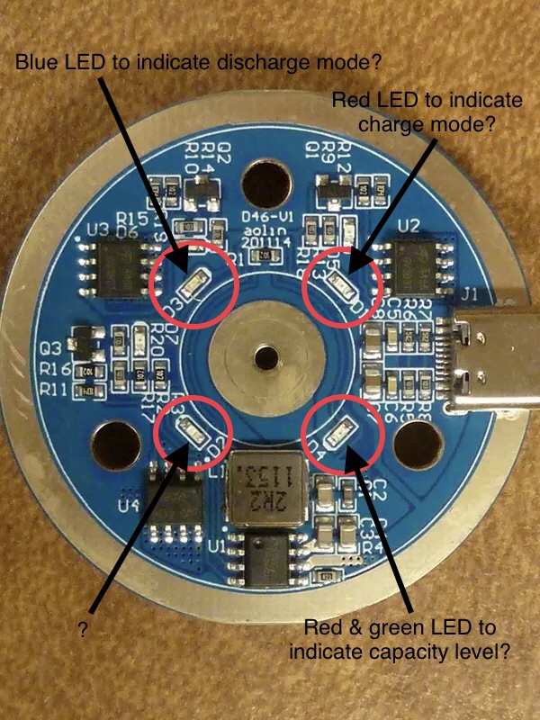
looks like there are 7 LED’s on that PCB actually, there are 4 in the middle and then 1 for each IC bank it appears, not sure what the smaller ones do but IIRC they were super dim and not visible through the center ring.
Tom, just realized that it seems like your going through some questionable times at work?- I hope all is well. I can imagine how stressful that is, thanks for keeping us in the loop, I’m sure your mind is on more important matters today. If I am wrong and misread your posts, then I apologize!