What the… Another version?! What are they doing?! At least it makes more sense than the previous version.
What in the world? There will soon be more LT1 variations than FW3A variations.
We had the original, the one that supports type C-C, the new one with screwed up pads and powerbank out, and now this one with pads but without the POT.
I’ve also seen this one which implemented a red channel but was never made, I assume due to them lacking the code
Unfortunately this is most likely an in-house (á’la Sofirn) variant of the classic version (i.e. no powerbank feature).
The only other place I’ve seen this design is an Aliexpress feedback entry from a Moldovan guy here from 05 Jul 2021 12:17.
And as you can see from both the product description and price of that Aliexpress listing, it is pretty clear that it is referring to the classic version.
I have the power-bank-equipped variant and its driver looks like the one in the orange lantern here.
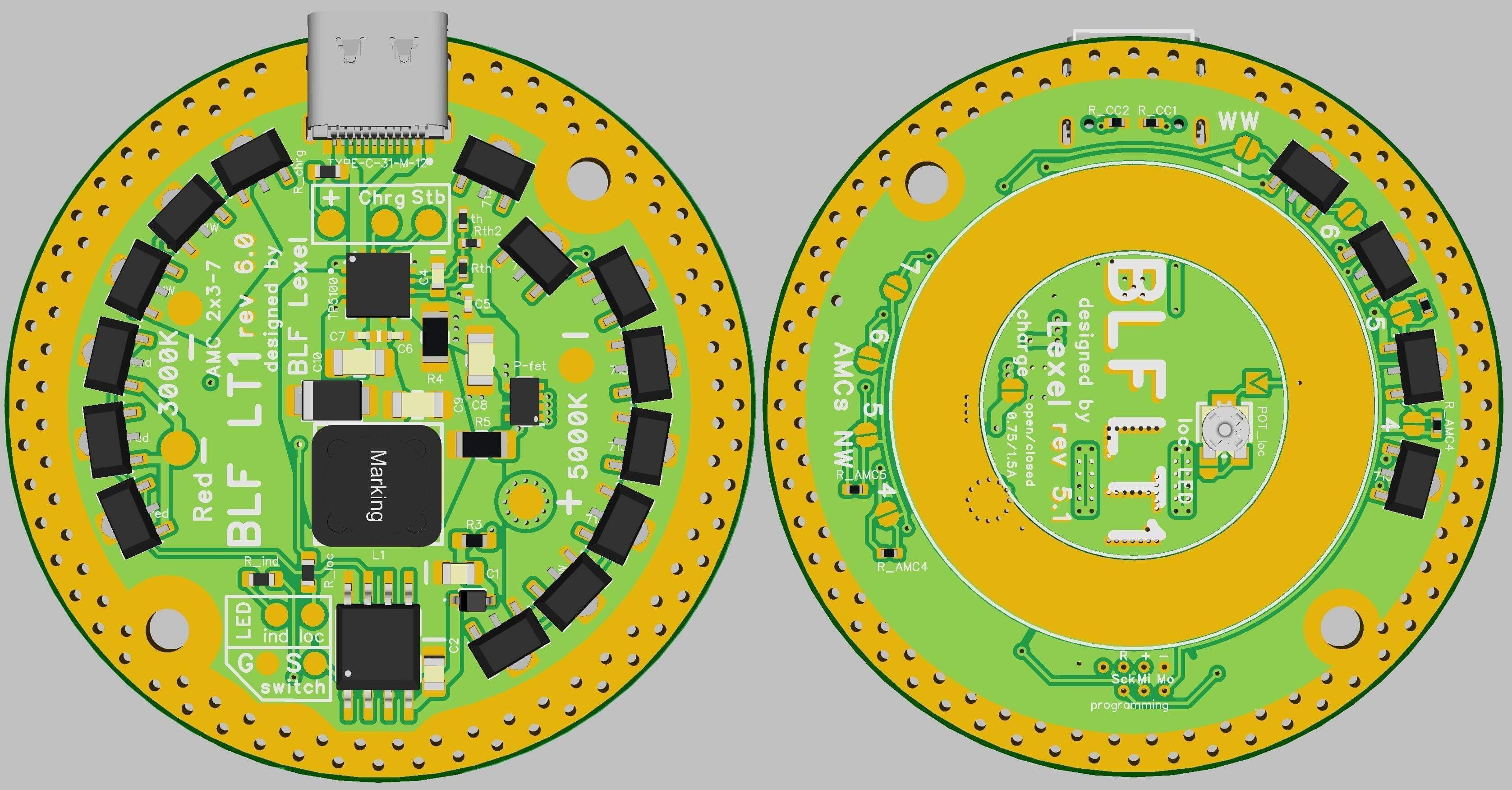
Of course, in theory, yours could be just another layout design around the same components, but it is unlikely, as the bottom layer of your driver PCB is rather suspiciously missing the very distinctive, rectangular grid-pattern of the thermal vias of the thermal pad of the powerbank controller IC. (The central, copper-colored rectangle with holes in the new, PB-equipped driver). Which indicates yours does not have such an IC. (Or if it does, they completely screwed up its thermal design ![]() )
)
If you want to approach the question from a more practical angle, I can recommend three things:
- If you have batteries and a Type-C to Type-C cable and a suitable USB device to be charged, then just plug them together and see what happens

- If you don’t have all of the above, only the batteries and A-to-C cable, then start charging the lantern, and watch the indicator LEDs. The TP5100 charger IC of the old design lights up the charging LED constantly. On the other hand, the IP5310 power-bank controller blinks it at 0.5Hz. I am intentionally not writing about LED colors, because there is no way for me to know what color LEDs Sofirn was using for what purpose in your case. Long story short: if your charging LED blinks, you probably have the PB feature, if it is constantly lit, you probably don’t.
- Unscrew the driver, take some pictures of its top side with all components markings visible, and send it here. If you do that, I’ll be able to tell you if you have the BP feature or not with absolute certainty. Hope it helps!
Thanks for the feedback, Lux.
FWIW, in my opinion, the whole programming-pad-layout thing is being blown way out of proportion… I mean come on guys, if anyone is nerdy enough (like me, for instance) to want to reflash the FW of a lighting apparatus, and know how to flash MCU FW in general, I think it’s safe to assume they also know their way around bench tools, soldering equipment, etc. and they can make their own programming fixture, or temporarily just jerry-rig the wires directly to the pads or the MCU pins. It’s an inconvenience, sure. But it is hardly the end of the world…
Yes, that was my greatest concern as well with the new model. (Whether the not too over-engineered thermal design of the LT1 can handle the extra dissipation by the additional 2x2 7135s…)
But I made some calculations, then performed some torture-tests yesterday which made me a bit more relaxed:
The top “cap” of the light has a surface area of 5850 mm2, which as a rule of thumb, should translate to a thermal resistance (Rth) in the neighborhood of 7 °C/W.
Rth (junction to solder point) of the LH351Ds 2.2 °C/W according to the datasheet.
Rth of a typical MCPCB is around 1 °C/W.
Rth of a reasonably applied half-decent thermal paste could be estimated around 0.3 °C/W
I=2450mA at full blast, while Vf of the LEDs (in worst case, i.e. when either extreme of the tint range is set) is 2.8V. Considering an efficiency of 70% that gives a power dissipation of about 4.8W, total.
If you put all this data together, mix some thermal design theory in it, you will receive a predicted heatsink temp of 62.6°C and LED junction temp of 79,4°C at an ambient temperature of 29°C.
The measurements I’ve done afterwards, seem to confirm this theory (heatsink temp of 66.0°C, junction temp 82.8°C, in a non-ventilated area at 29°C ambient):

What I actually measured are the head/heatsink temps. (Simultaneously via non-contact thermometer, and K-type thermocouple, always taking into account the highest reading) The junction temps are just projected from the heatsink temps. There is no way to measure them directly. However if anyone wants to determine their values more accurately, they could measure the MCPCB temp instead of the heatsink and offset the measured values by 4.8W*2.2 °C/W= 10.56°C. This way you could eliminate the potential inaccuracies stemming from the estimated MCPCB and thermal paste Rths.
Now, 82.8°C might sound awful, but actually it is not. The “design temperature” of today’s power LEDs (LH351D included) is 85°C. This is where the manufacturers expect OEMs to run them in their end-devices. This is the temp they are binned at, this is also where their environmental stress tests are performed. It is a perfectly safe temp for our LEDs (the top end of their operating junction temp is 105°C!).
I also measured the temperature of the battery tube. Its 44°C is also not catastrophic, most Li-ion cells today allow a max discharge temp of 60°C. However I am sure it will have some lifetime penalties if the cells are subjected to it on a regular basis: Some researchers say every 10°C above room temp reduces the lifetime cycle rating by ~25%. I can neither confirm nor deny if this statement is accurate though… maybe someone with more practical experience with the quirks of Li-ion cells can.
Thank you, great analysis! Still, 70 °C is pretty hot when you touch it. ![]()
I know, I learned that the hard way ![]()
Joke aside, even the 45C handle/tube temperature is not that pleasant on the long term. It’s not burning, but your palm will sweat like a pig, that’s pretty much guaranteed ![]() So in a scenario when you intend to hold the lantern in your hands for prolonged periods, it might be good idea to step it down a bit.
So in a scenario when you intend to hold the lantern in your hands for prolonged periods, it might be good idea to step it down a bit.
Thanks for such a detailed reply! Still waiting on my C-A adapter but I found a USB C-C cable and connected it to an old BLF LT1. It powers it in headless mode and when the battery tube is screwed in, the new LT1 button color changes to blue-amber, I guess indicating charging? When the New LT1 is connected to a power source, the button does not blink. I also have the same new/short manual that was posted recently.
This is specifically the model I ordered:
https://sofirnlight.com/products/new-version-blf-lt1-lantern-with-anduril-20-power-bank-function
“Black-NewVersion-with-Battery: LT1 new version + 4x batteries (inserted) + USBA to USBC cable”
I can unscrew the driver if you want, but hesitated since I didn’t know how hard it would be to get back together :nerd_face:
I went ahead and did it. Sorry for the low quality, it was hard to keep it positioned correctly and snap the photo.

I’m more confused than ever about the LT1. Does this “Sofirn 1.0” version act as a power bank or not? Why are there only two bridges for the 7135 config?
It definitely has power output.

This Sofirn V1.0 seems to be the best version. Powerbank function, pogo pins, and 7135 pads, and an orange led instead of that green one.
Interesting. I was feeling like maybe I got the short end of the stick somehow. When it’s fully charged, the light does turn green
Regarding the pogo pins, there is only ONE readily available pogo pin adapter in the market and that is the one Hank sells, at a good price. Why won’t Sofirn make their pads compatible with that adapter?
Are you listening Sofirn? Either sell us a pogo pin adapter compatible with your design or change your design to make it compatible with Hank’s adapter.
This does not affect me personally, I can easily remove 2 screws, turn the driver around and flash the attiny85 with a SOIC clip.
An orange switch is more soothing and in line with the LT1’s warm emitters imo. The LEDs turning green to indicate the completion of charging is normal and desired.
This was the format wars of our flashlights. The 3+3 is the doing of Lexel, the original designer of this driver and many others at blf. It just so happened that hank had a different one, and so the pogo key you can get made at oshpark can be made to work for either.
I bought my new LT1 a few days ago from sofirnlight.com directly, using this link:
https://sofirnlight.com/products/new-version-blf-lt1-lantern-with-anduril-20-power-bank-function
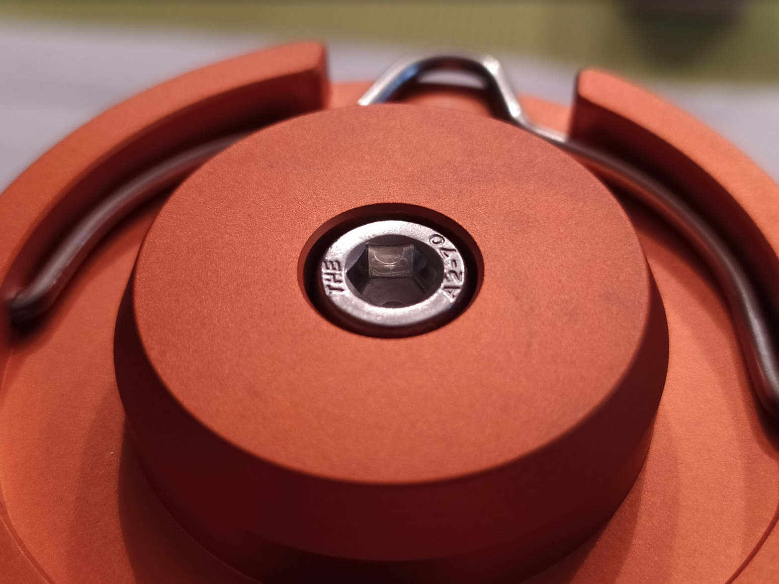
I am not sure if this will stir things more up but this is how it looks like:


I know, I am getting OCD / nitpicky again ... can't help making suggestions ... but ... maybe Sofirn can have a closer look at the CNC burring of the top panel and the anodizing finish. It has a very rough/sharp line if you slide with your finger over it. The orange on the top plate looks somehow stained/imperfect. The picture does not show it as good as I can see it with bare eyes, though.

As much as I agree with you...
I doubt that will happen anytime soon. Redesigning the driver schematics once again will probably cost a lot. Retrofitting all produced units of the new LT1 batch is not an option, either. I can only guess but I assume they made a big lot of 1,000 pcs in black and orange. Offering us a pogo pin adapter would be a more feasible option but how many units would be need to be sold to meet break-even? How difficult would it be for Sofirn to make, let's say a thousand pogo pin adapters including sourcing raw materials, train their staff for assembly etc.? How big of a problem is it that we now need to have two different adapters as there are two layouts available?
Thanks for the feedback, this is so interesting!!!
It looks as if they chose a different powerbank controller IC for this version. The inductors do not mach either between the two boards, yours is 2.2uH, mine is 1.0uH. I guess the controller in yours uses a lower switching frequency.
Unfortunately, in the photo, the PB IC (seated between the USB socket and inductor with the “2R2” marking) is mostly covered by the red wire, so I cannot make out its make and model.
If you are feeling adventurous, you could check it again and write down the markings on it ![]()
A am a bit confused by the LED “user interface” of your variant.
Do I understand correctly that the indication on the new LT1 was different when it powered the old “tubeless” LT1 VS when it powered the old LT1 with its tube and batteries installed??
Can you summarize what LED behavior you observed?
Mine looks like this:
table(table#posts).
|LED color|What it indicates|
|Green|Aux light (configurable via Andúril: off/lo/hi/blink)|
|Blue blinking|Lantern being charged|
|Blue steady|Lantern fully charged|
|Amber steady|Type-C power output active|
|Amber blinking (*)|Battery low|
(*) I have not yet seen the low battery warning in action, but according to the IP5310 datasheet, it exists, and should kick in at 2.95V. (I have not yet exhausted my cells below that level.)
A assume your aux light is orange and the green & blue ones are the charging and output indicators (most probably tied to the PB IC directly). Am I correct about the aux led? Do the other two never blink, just show steady blue/green?
I cannot agree with you more… The green aux LED of the BLF-LT1-A2 drives me nuts. I’ll definitely replace the switch LEDs next time I have some free time.
Speaking of… Has anyone had a look at what size they are? 0603?