I am not sure if this will stir things more up but this is how it looks like:
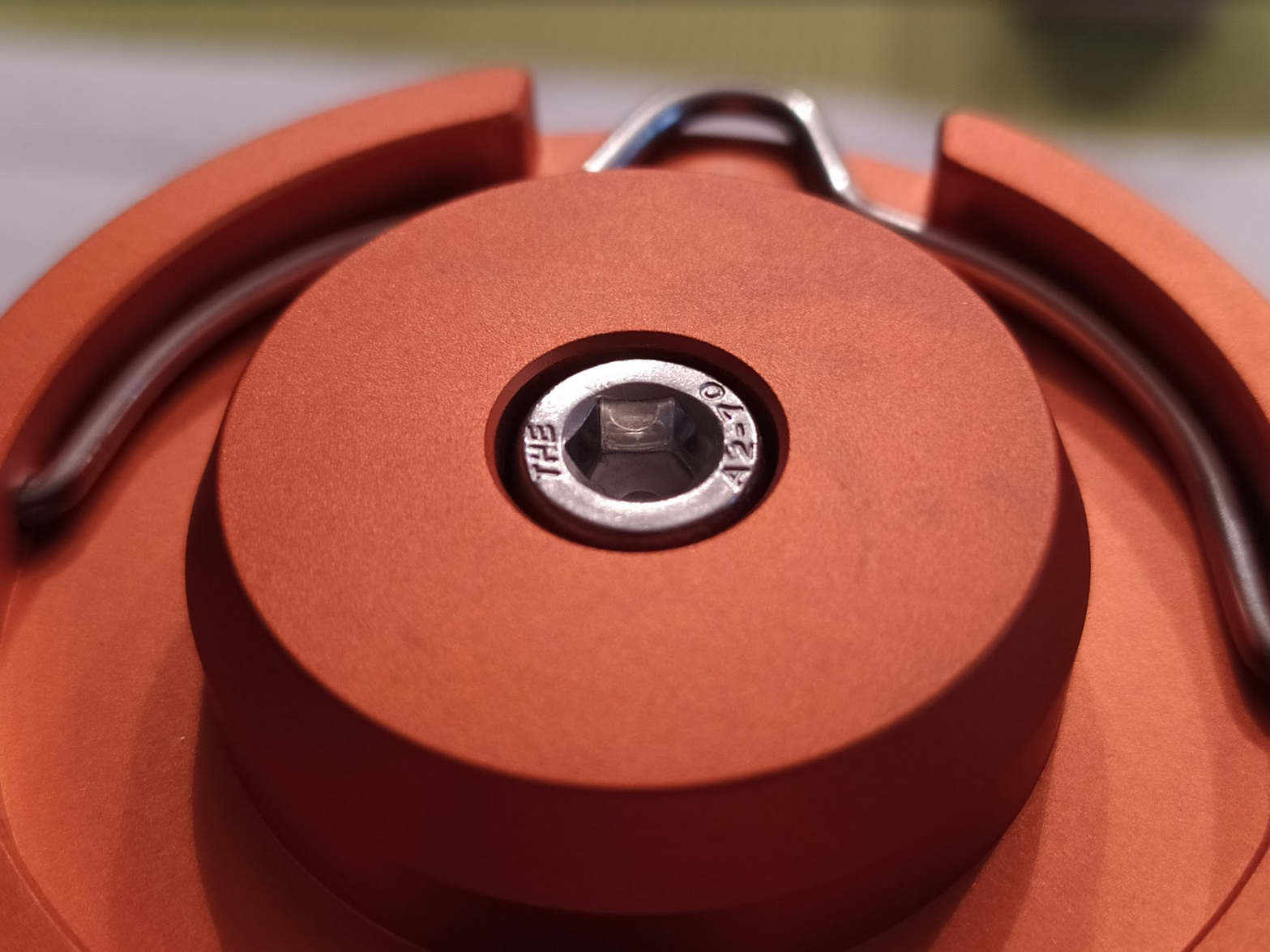
I know, I am getting OCD / nitpicky again ... can't help making suggestions ... but ... maybe Sofirn can have a closer look at the CNC burring of the top panel and the anodizing finish. It has a very rough/sharp line if you slide with your finger over it. The orange on the top plate looks somehow stained/imperfect. The picture does not show it as good as I can see it with bare eyes, though.
I doubt that will happen anytime soon. Redesigning the driver schematics once again will probably cost a lot. Retrofitting all produced units of the new LT1 batch is not an option, either. I can only guess but I assume they made a big lot of 1,000 pcs in black and orange. Offering us a pogo pin adapter would be a more feasible option but how many units would be need to be sold to meet break-even? How difficult would it be for Sofirn to make, let's say a thousand pogo pin adapters including sourcing raw materials, train their staff for assembly etc.? How big of a problem is it that we now need to have two different adapters as there are two layouts available?
Thanks for the feedback, this is so interesting!!!
It looks as if they chose a different powerbank controller IC for this version. The inductors do not mach either between the two boards, yours is 2.2uH, mine is 1.0uH. I guess the controller in yours uses a lower switching frequency.
Unfortunately, in the photo, the PB IC (seated between the USB socket and inductor with the “2R2” marking) is mostly covered by the red wire, so I cannot make out its make and model.
If you are feeling adventurous, you could check it again and write down the markings on it
A am a bit confused by the LED “user interface” of your variant.
Do I understand correctly that the indication on the new LT1 was different when it powered the old “tubeless” LT1 VS when it powered the old LT1 with its tube and batteries installed??
Can you summarize what LED behavior you observed?
Mine looks like this:
table(table#posts).
|LED color|What it indicates|
|Green|Aux light (configurable via Andúril: off/lo/hi/blink)|
|Blue blinking|Lantern being charged|
|Blue steady|Lantern fully charged|
|Amber steady|Type-C power output active|
|Amber blinking (*)|Battery low|
(*) I have not yet seen the low battery warning in action, but according to the IP5310 datasheet, it exists, and should kick in at 2.95V. (I have not yet exhausted my cells below that level.)
A assume your aux light is orange and the green & blue ones are the charging and output indicators (most probably tied to the PB IC directly). Am I correct about the aux led? Do the other two never blink, just show steady blue/green?
I cannot agree with you more… The green aux LED of the BLF-LT1-A2 drives me nuts. I’ll definitely replace the switch LEDs next time I have some free time.
Speaking of… Has anyone had a look at what size they are? 0603?
I have several motor vehicles. None of the wheels are interchagable. I need different size socket wrenches to fit the nuts. Two of the vehicles that have the same bolt pattern use different offsets.
Why would I expect two different makers of anything to make their units interchange with another maker? That only happens when there are long drawn out negotiations and maybe a trade group involved. Like USB-C…. and even then somebody, or many somebodies, mess up.
I‘m sorry, did I get this right? The new (orange) LT1 uses a GREEN, not amber for standby mode? I did not power up mine yet but this would definitely be a bad surprise to me.
I try to persuade Barry to revise the indicator scheme as follows:
Green: Lantern fully charged
Green blinking: Lantern being charged
Blue steady: Lantern in reverse charge mode (powerbank mode)
Blue blinking: Low voltage
Amber: Standby switch illumination (off/low/high/beacon) as usual in older revisions of LT1
Any better ideas? I guess red is not available since they now have blue included?
IMHO, green works great for flashlights but lanterns are something your eyes are often looking at. So, a warm and less distracting color like yellow/red works best.
Coincidentally, this is exactly how I want to rewire mine at the moment
At some point I planned to throw out the blue LEDs altogether and go with a Green-Red-Amber(as standby) scheme, but now I’ve grown a bit fond of them.
Do you know by any chance what series resistor (designated “R_ind” in the silk screen) value was used for the amber LED in the original drivers?
Unfortunately I don’t own an old LT1 to check…
Sorry, I wish I could help but I am not that skilled. :( Lexel as the original driver designer seems unavailable for months now. Maybe DBSAR or someone else can chime in to check for the right resistor.
Yeah it showed different colors when it was tubeless vs. tubed.
Here is the old LT1 (left) being charged by the new LT1 (right)
Here is the old headless LT1 (left) being powered by the new LT1 (right)
And here are the LED states i’ve seen so far:
orange steady= standby
orange steady + small red light= charging
green steady=connected to power source + fully charged
blue+orange=charging another device
I haven’t yet seen any blinking so far.
I’ll try to get it back open again later and find that IC # for you. Worried about having to resolder those wires!
That inconsistency in the power output indication in the photos must be related to the built-in load detection feature of the PD controller. The only significant difference in the two scenarios from the controller’s POV is the required current. Which is relatively high in the “tubed+standby” case and very low in the “tubeless+standby” case. The latter was probably not high enough to trigger the load detection, which usually has a threshold around 50mA. Basically, in the tubeless case, the new LT1 did not notice it was connected to something.
Thanks. If you do, try to take multiple pictures from multiple angles for a better success rate. And be careful with those wires
I’m really confused now…
So many variations.
Is the original LT1 version 1 capable of being programmed to Anduril 2.0? If so, I may go that route. I’m not needing my LT1 to double as a power bank. I would NOT want the active power/standby switch light to be green, as showing in the newer release. That would annoy me to no end…
Yeah if you can upgrade it to 2.0 that seems to make the most sense for you. But just to be clear, the powerbank version I got maintains the orange standby light.
Cool! Thanks for the photo.
We were right then, that is indeed a completely different controller. From another manufacturer (which I admit, I have not even heard of).
What’s very strange about that IC is that it is laking any connection with the CC pins in the Type-C connector, which the whole power-role detection and switching scheme of USB Type-C is based on.
It handles all that somehow solely based on the VBUS (device power) pin. Not how the guys at USB-IF intended it, for sure. But hey, if it works, we cannot complain, right
I assume this variant of LT1 driver has fixed resistors wired to he CC lines. Meaning that it advertises itself in a fixed, hardcoded role. But this also means that its actual role and advertized role is going to be inconsistent in 50% of the cases: either when sourcing or sinking power. That should be fine for “dumb” devices (chargers w USB-A sockets, old LT1) but could be problematic with “real” Type-C / PD devices, which actually make extensive use of the CC pins.
I hope I am wrong about that, but nevertheless it could not hurt to do some tests with different devices, with a C-to-C cable, to see how it behaves with them.
With the other driver variant, there are no such concerns, its controller (IP5310 from Injoinic) is a “real” Type-C device, with built-in CC-pin handling logic, Type-C DRP Try-Src statemachine, all bells and whistles.
I have some headphones I could try charging with it. Would you say that this setup could potentially damage real Type-C devices? Would it harm something like an iphone, which still uses lightning cables?