Need Advice - SFT40 Emitter Swap - EA01s (fail, so far)

Hey there,

so i am starting this thread because i was photo documenting my emitter swap of the sst40's out of my Astrolux EA01s while putting the SFT40 emitters in. i have many more photos but at this point, this thread is not about the success i have had swapping the emitters and showing that to you.

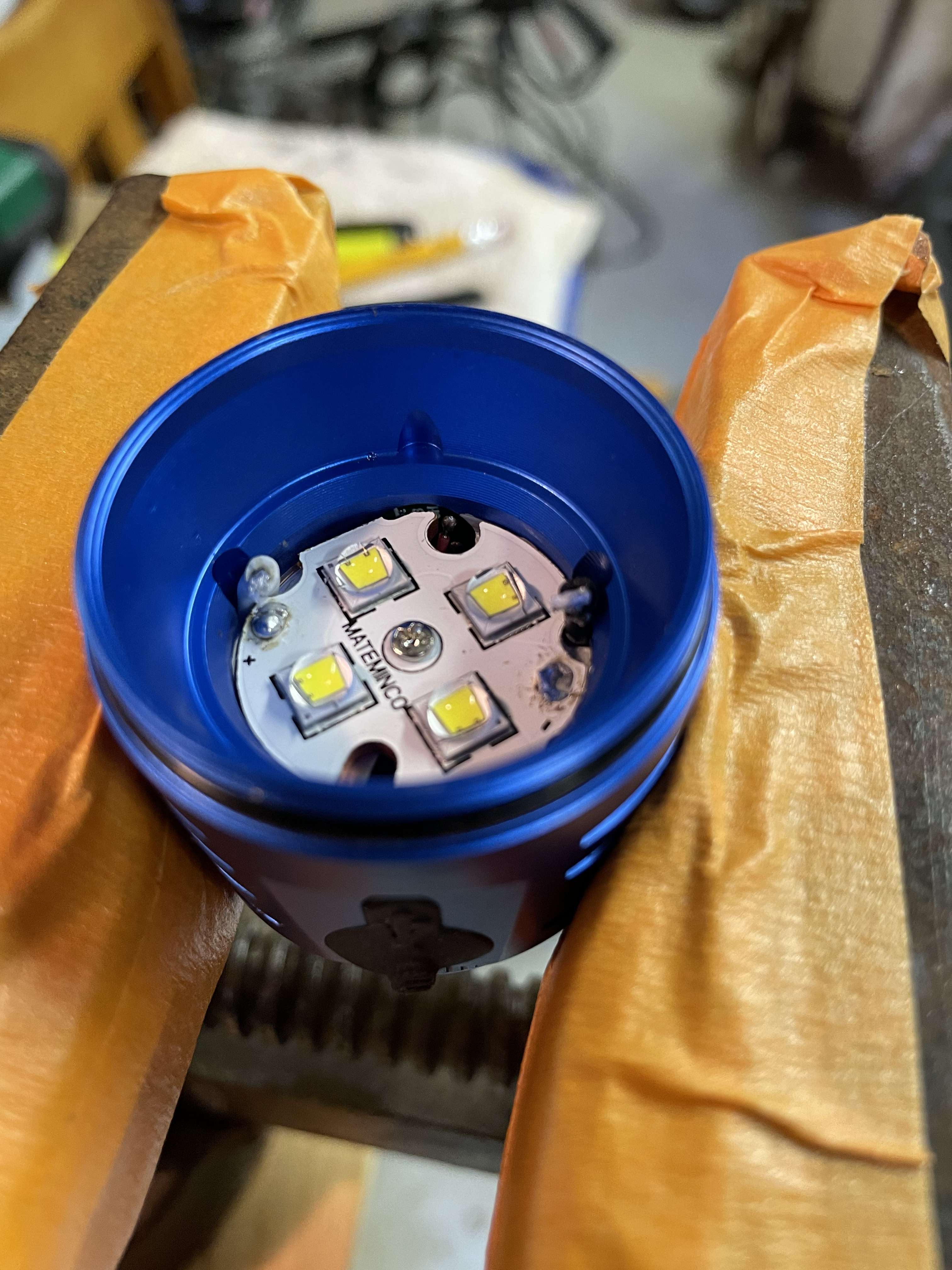
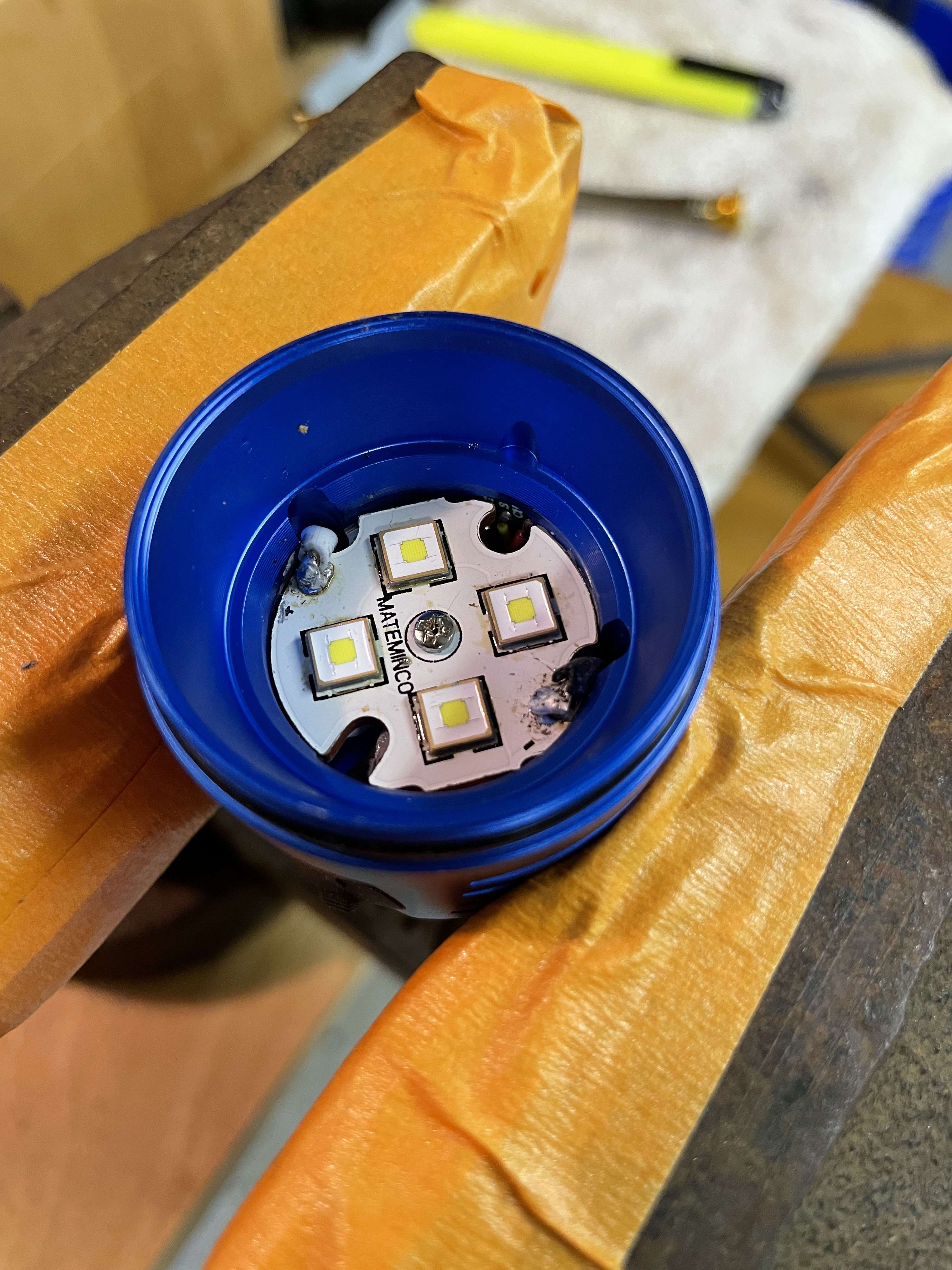
After flowing the SFT40 onto the stock EA01s mcpcb (pic shows them on the board) , and resoldering the mcpcb back into the light, the "failure" happened.

Before reinstalling the reflector, centering rings, lense and bezel i screwed the head back onto the battery tube, as i always do, to make sure everything is working OK (even tho i tested the emitters with the DMM to make sure i flowed them in the right orientation).

Once i tightened down the head to the battery tube, the light goes into, what i can only describe, Direct Drive Mode! the switch does not "work" at all, meaning i cannot use the switch to dim the light, turn the light off, or even do a reset. the light is just ON, full blast, and there is no stopping it until i unscrew the head or tailcap to turn it off..

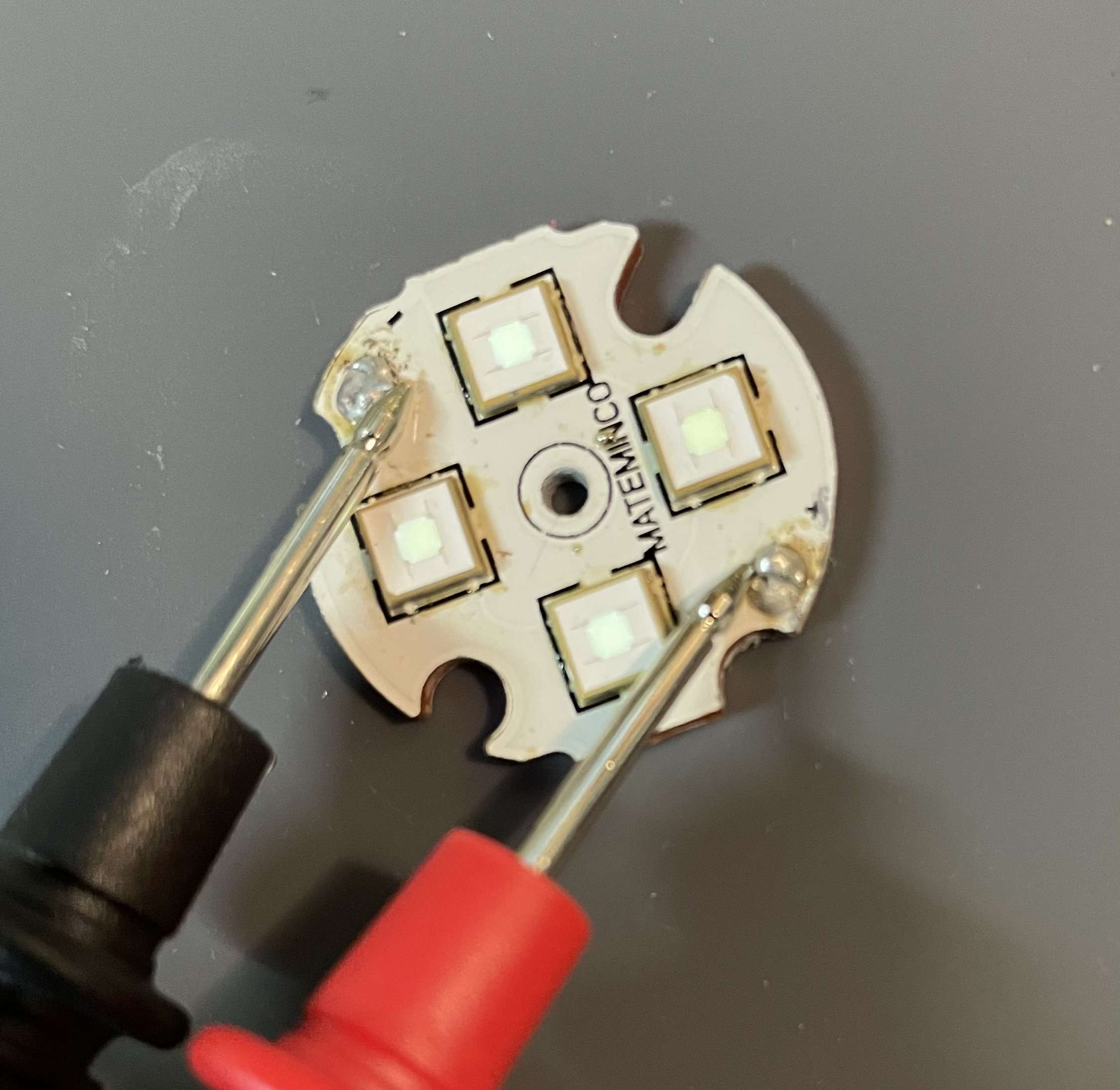
I can attach more pictures, but does anyone have any idea what i may have EFFED up?? I removed an dresoldered the mcpcb about 3 more times and it does it every time. I kindve split the negative driver-to-mcpcb wire coating, so i used heat shrink to cover the negative wire better to make sure it wasnt contacting the flashlight body or the mcpcb. it didnt help. I sanded down the edges of the mcpcb as it was very tight fitting and i was worried maybe i did not center it 100% OK and it was touching the edges o fthe head of the light and making contact and thus bypassing the switch (I don't know if that is even something that can happen).

A couple of notes i think may be significant:

  1. the negative wire was VERY difficult to originally desolder. it was "tight" or maybe "hard" would best describe it.. i had to really work at removing it from the mcpcb the first time i removed it. hence why i split the coating a little and had to heat shrink it..
  2. the switch wires are exposed through a little whole drilled into the shelf, and they are VERY close to making contact with the mcpcb when it is intsalled. this is another reason i sanded down the whole edge of the mcpcb, to make it smaller (maybe 1-2mm total) and ensure it was not contacting the switch wires / solder points. it does Not look like they are contacting each other.
  3. I checked the VF of the sst40 and the sft40 on the data sheets, and they look to be exactly the same. i didnt know if maybe that could have something to do with it..
  4. does one of those SFT40's look a little duller than the other 3? i thought it did, and i put the mcpcb back onto the hotplate and removed that one, and added more solder paste and reinstalled, making sure to get the extra out by tapping it but also make sure it still sprung back to its place. after all of that, it still seemed a little less bright. I don't know if that matters to this situation, but i did notice it.

I'm at a loss. if i cannot figure it out or if there is no clear answer, i am going to reinstall the SSt40's and if that doesnt work i going to remove the driver, which im sure at that point i will ruin it. lol. oh boy.. brand new light too, this is what i get! thanks in advance anyone who can help!

Sounds like you connected the led-minus to the core of the board (which is often in direct electrical connection via the body to the batt-minus), either a solder bridge under a led, or by sanding the edge of the board copper bits are connecting the led-minus trace over the insulation layer to the core of the board (copper behaves like a paste when sanded).

Sorry If I missed it but did you check for continuity between the LED negative wire and the mcpcb/body

With the DMM or at full blast ? At low current it’s normal.

You probably have a short to ground as djozz said. It only takes a tiny spec of misplaced solder or an errant wire. Check your connections very carefully and try again. Use leaded rosin core solder and add flux if possible. You really need to crank up your iron to solder on those thick mcpcbs when installed in the host since it’s drawing away the heat. I use kapton tape to cover any exposed joints that may habe potential for shorting.

thabk you I will check for that! The heat shrink I added maybe didn't cover it enough. But I didn't know that about the board and negative terminal. Great info!

you didn't miss anything, I will definitely check for this. And it's good to know that it's normal for one to maybe look dimmer through low current/DMM. Thank you !

awesome, thanks for the tip. I'll check it out tomorrow when I have time.

Hope it works out and we get a beamshot :slight_smile:

Yep, as has been mentioned, I’d bet there is a solder bridge under one of the led’s. Had it happens couple of times. You shouldn’t have continuity between either the positive or negative points on the mcpcb and the core of the mcpcb itself. Try doing the reflow again and be sure to do the all important tap on each LED to squeeze out excess solder.

As others have mentioned, the most likely scenario is a short to ground.

In my experience, this is probably caused by a bad reflow under one of the LEDs between the negative pad and the central pad. Even the tiniest amount of solder bridge is enough to cause a short.

To avoid this, after every reflow and before installing the star in the light, I do the following in order:

  • Visual Inspection. I use a magnifying glass and a small aspheric lens to get a close look at the solder at the edges of each LED. The goal is to make sure everything looks about right and there are no significant air gaps.
  • Check for shorts. I place the star on top of the anvil of a small steel table vise. I have an ancient digital multimeter that has a mode that beeps when there is no resistance between the 2 probes. I touch one probe to the anvil, then the other to each of the 2 bondpads on the star. If there is no short, the multimeter should not beep.
  • Check for function. I have an old 14500 in a battery carrier with 2 wires coming out. I touch the wires to the bondpads on the star to make sure the LEDs all light up and were installed the correct direction.

I have one of these led testers to check workings and shorts just after reflow of a led. I modded it a bit: changed the momentary switch for an on-off clicky.

wow, thank you all for your help. this has been awesome, and very informative!

sorry to leave every one hanging but i wont have time to inspect the mcpcb / reflow until tomorrow morning most likely.

I definitely believe you all are right though with a solder bridge under the LED between the negative and main pad.

I am really appreciative that TMAXXJJ stated that specifically (sorry if someone else did before them), because honestly before you mentioned that it was most likely UNDER the LED, i was going to start inspecting the negative wire from the driver. but this made me feel hopeless because before i posted this i literally inspected the negative driver to mcpcb wire for 15 minutes and found nothing or no point of a short. so i was not excited to look there again.

I definitely believe i have a short under an LED - this is why:

I did my taps on the LED to make sure excess solder was removed and the LED's were laying flat for best thermal transfer to the pad. But i also do the "push test" to make sure the LED "bounces back" into place, which as i've learned is a good indication that there is enough solder applied to the LED. well i always do the push test along the "plane" if you will of the direction going "with" the direction of the pads. Because the LED's directions change to accomodate the +/- pad layouts, i accidentally pushed one or maybe two LED's "against" the underside pads of the LED (or perpendicular to them) which i feel could've smeared solder between positive and main as well as main and negative.

I hope that explanation makes sense. i should've just drawn a simple sketch to explain what i just typed above ^. Anyway, i think you all are 100% correct, there is a solder bridge of some sort under at least one of my LED's.

Hopefully the copper braided wire i have from MtnE will work well enough as a "wick" to remove the excess solder to let me start again... any suggestion on wicking excess solder when you dont have any solder wick? Ive noticed it can get messy and just spread the solder around if your not prepared to start removing some excess once you get the mcpcb heated up.

also, if i have one of the LED"s polarity turned opposite would that cause this problem? the one thing about the SFT40 is i cannot tell at all which side is + and which is - ... There are no dots, lines, or any visual queues like there are on almost all other LED"s i've worked with..

I haven’t worked with these LED’s yet, but is there any markings on the pads underneath to denote polarity? Failing that, looking at your pictures there’s a cut out in the very corner of each LED. I bet that marks the anode or cathode.

With regards to the solder bridge, before you reflow the LEDs check for continuity between the positive and the underside and the negative and the underside of the MCPCB. This should confirm you have a bridge. If you have, remove each one and check. If you have a fine point for your soldering iron, you should be able to remove it with that. Then try your reflow again. If you have excess, tapping each LED should squeeze out any excess and you’ll end up with little balls to the sides of the pads. Let us know your results!

Do not rule out a possible short between trace and core because of the sanding work you have done on the PCB.

Ok thank you for this info! so you said:

If i have a solder bridge when checking pos/underside of mcpcb and neg/underside, what will happen? the LED"s will light up? or the DMM will react? Sorry, i do understand what you mean by checking the continuity of the pos/underside and neg/underside, but what will i see if there is a solder bridge?

Thanks! i will definitely let you all know!

so i hope i didn't create a short, but i will say - all of the problems were happening (the constant ON, direct drive) before i sanded anything, at all. i only sanded because in my limited lack of knowledge thought maybe the problem was happening because the edge of the mcpcb was making contact with the inside of the flashlight head so i made the diameter smaller to eliminate contact. I've come to find out that didn't matter because inside of the head is cleanly anodized (except for the shelf, of course). So my problem existed before my sanding, but now i may of created another problem of course by creating a short. let's hope not! if so, anyone have the Mateminco rep's contact info? LOL.. lets i hope i can fix this though, and I dont need a new mcpcb...

Basically, there shouldn’t be continuity. So if your multimeter beeps (or however your multimeter registers continuity) then you know there’s a problem.

ahh, got it! yup, that makes sense! lol...

(we really need a crazy eye emoji, because half the time i ask a question i could use it lol)

Being a cautious person I vote the same as the majority: there is a short (somewhere) between the black lead and the body. I would check every point where that can happen.
1 Starting at the (downside) of the lead itself. A number of times the insulation of the black lead was torn against a sharp edge on the leadboard.
2 Check if the leadboard has (a bit) “room to move” in all directions. Thus preventing that a sharp edge on the ledboard can touch the body because of damaged ano.
3 Et cetera, just work your way up to the leads themselves.