Sorry If I missed it but did you check for continuity between the LED negative wire and the mcpcb/body
With the DMM or at full blast ? At low current it’s normal.
Sorry If I missed it but did you check for continuity between the LED negative wire and the mcpcb/body
With the DMM or at full blast ? At low current it’s normal.
You probably have a short to ground as djozz said. It only takes a tiny spec of misplaced solder or an errant wire. Check your connections very carefully and try again. Use leaded rosin core solder and add flux if possible. You really need to crank up your iron to solder on those thick mcpcbs when installed in the host since it’s drawing away the heat. I use kapton tape to cover any exposed joints that may habe potential for shorting.
thabk you I will check for that! The heat shrink I added maybe didn't cover it enough. But I didn't know that about the board and negative terminal. Great info!
you didn't miss anything, I will definitely check for this. And it's good to know that it's normal for one to maybe look dimmer through low current/DMM. Thank you !
awesome, thanks for the tip. I'll check it out tomorrow when I have time.
Hope it works out and we get a beamshot ![]()
Yep, as has been mentioned, I’d bet there is a solder bridge under one of the led’s. Had it happens couple of times. You shouldn’t have continuity between either the positive or negative points on the mcpcb and the core of the mcpcb itself. Try doing the reflow again and be sure to do the all important tap on each LED to squeeze out excess solder.
As others have mentioned, the most likely scenario is a short to ground.
In my experience, this is probably caused by a bad reflow under one of the LEDs between the negative pad and the central pad. Even the tiniest amount of solder bridge is enough to cause a short.
To avoid this, after every reflow and before installing the star in the light, I do the following in order:
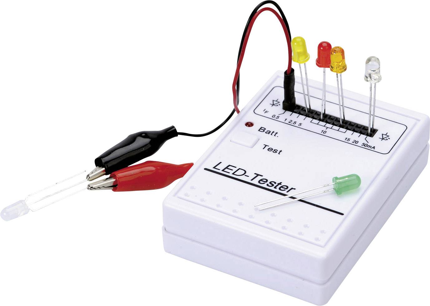
I have one of these led testers to check workings and shorts just after reflow of a led. I modded it a bit: changed the momentary switch for an on-off clicky.
wow, thank you all for your help. this has been awesome, and very informative!
sorry to leave every one hanging but i wont have time to inspect the mcpcb / reflow until tomorrow morning most likely.
I definitely believe you all are right though with a solder bridge under the LED between the negative and main pad.
I am really appreciative that TMAXXJJ stated that specifically (sorry if someone else did before them), because honestly before you mentioned that it was most likely UNDER the LED, i was going to start inspecting the negative wire from the driver. but this made me feel hopeless because before i posted this i literally inspected the negative driver to mcpcb wire for 15 minutes and found nothing or no point of a short. so i was not excited to look there again.
I definitely believe i have a short under an LED - this is why:
I did my taps on the LED to make sure excess solder was removed and the LED's were laying flat for best thermal transfer to the pad. But i also do the "push test" to make sure the LED "bounces back" into place, which as i've learned is a good indication that there is enough solder applied to the LED. well i always do the push test along the "plane" if you will of the direction going "with" the direction of the pads. Because the LED's directions change to accomodate the +/- pad layouts, i accidentally pushed one or maybe two LED's "against" the underside pads of the LED (or perpendicular to them) which i feel could've smeared solder between positive and main as well as main and negative.
I hope that explanation makes sense. i should've just drawn a simple sketch to explain what i just typed above ^. Anyway, i think you all are 100% correct, there is a solder bridge of some sort under at least one of my LED's.
Hopefully the copper braided wire i have from MtnE will work well enough as a "wick" to remove the excess solder to let me start again... any suggestion on wicking excess solder when you dont have any solder wick? Ive noticed it can get messy and just spread the solder around if your not prepared to start removing some excess once you get the mcpcb heated up.
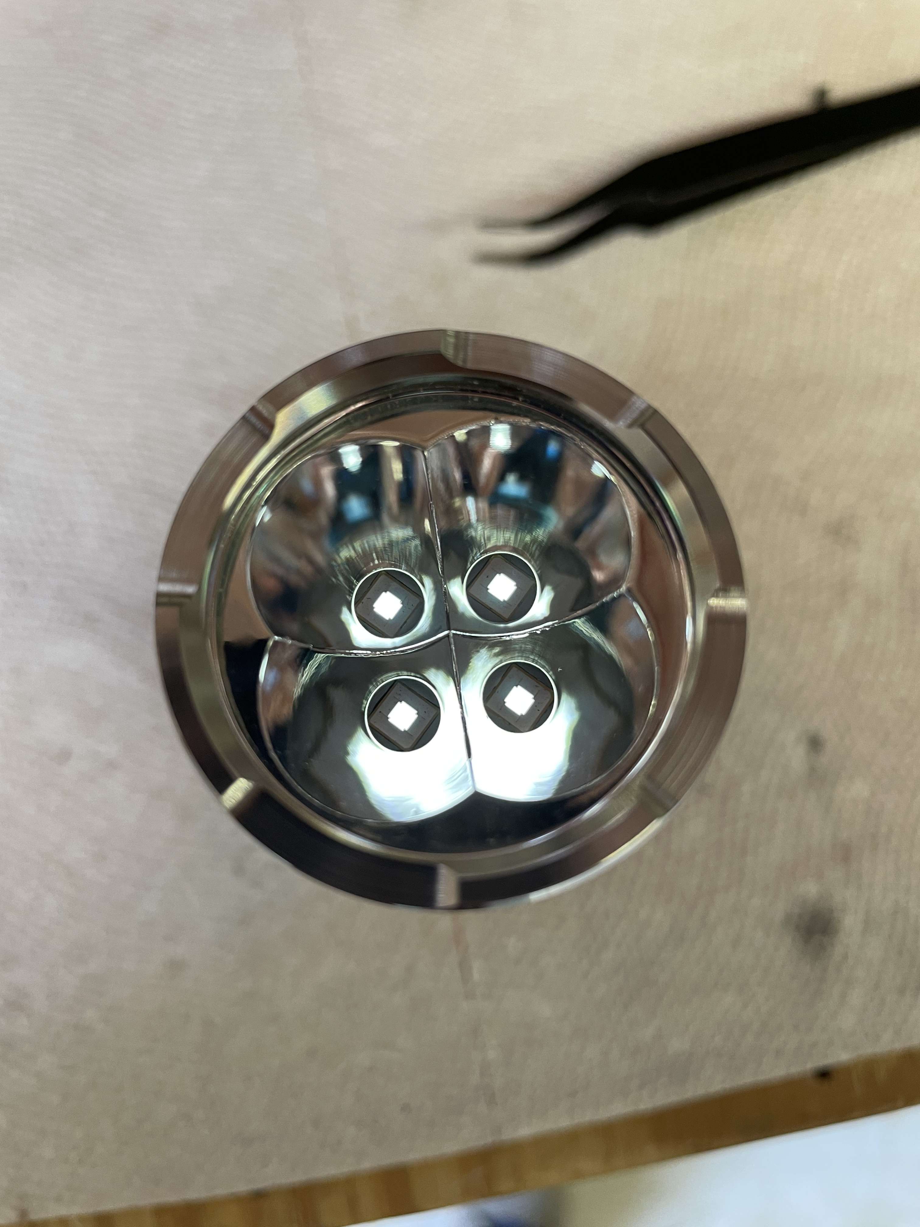
also, if i have one of the LED"s polarity turned opposite would that cause this problem? the one thing about the SFT40 is i cannot tell at all which side is + and which is - ... There are no dots, lines, or any visual queues like there are on almost all other LED"s i've worked with..
I haven’t worked with these LED’s yet, but is there any markings on the pads underneath to denote polarity? Failing that, looking at your pictures there’s a cut out in the very corner of each LED. I bet that marks the anode or cathode.
With regards to the solder bridge, before you reflow the LEDs check for continuity between the positive and the underside and the negative and the underside of the MCPCB. This should confirm you have a bridge. If you have, remove each one and check. If you have a fine point for your soldering iron, you should be able to remove it with that. Then try your reflow again. If you have excess, tapping each LED should squeeze out any excess and you’ll end up with little balls to the sides of the pads. Let us know your results!
Do not rule out a possible short between trace and core because of the sanding work you have done on the PCB.
Ok thank you for this info! so you said:
If i have a solder bridge when checking pos/underside of mcpcb and neg/underside, what will happen? the LED"s will light up? or the DMM will react? Sorry, i do understand what you mean by checking the continuity of the pos/underside and neg/underside, but what will i see if there is a solder bridge?
Thanks! i will definitely let you all know!
so i hope i didn't create a short, but i will say - all of the problems were happening (the constant ON, direct drive) before i sanded anything, at all. i only sanded because in my limited lack of knowledge thought maybe the problem was happening because the edge of the mcpcb was making contact with the inside of the flashlight head so i made the diameter smaller to eliminate contact. I've come to find out that didn't matter because inside of the head is cleanly anodized (except for the shelf, of course). So my problem existed before my sanding, but now i may of created another problem of course by creating a short. let's hope not! if so, anyone have the Mateminco rep's contact info? LOL.. lets i hope i can fix this though, and I dont need a new mcpcb...
Basically, there shouldn’t be continuity. So if your multimeter beeps (or however your multimeter registers continuity) then you know there’s a problem.
ahh, got it! yup, that makes sense! lol...
(we really need a crazy eye emoji, because half the time i ask a question i could use it lol)
Being a cautious person I vote the same as the majority: there is a short (somewhere) between the black lead and the body. I would check every point where that can happen.
1 Starting at the (downside) of the lead itself. A number of times the insulation of the black lead was torn against a sharp edge on the leadboard.
2 Check if the leadboard has (a bit) “room to move” in all directions. Thus preventing that a sharp edge on the ledboard can touch the body because of damaged ano.
3 Et cetera, just work your way up to the leads themselves.
There’s a notch on one vertex. You can see it in your pictures. This is the anode side. I think you got it right.
The SFT-40 has two pads, anode and large cathod. So, on a MCPCB for the SST-40, you bridged cathod and copper core, or am I completely mistaken here?
Alright, I Finally got back to it this morning- and I believe you folks were right! It's working!
So I removed the mcpcb, and started by checking the heat shrink I put on the negative lead, it was intact and covering it fine.
I then threw the mcpcb back on the hot plate and got to cookin' ! I removed all 4 leds, checked to make sure there was no solder smeared between the (3) pads for each led (main, pos, neg) and also checked the back of each of my sft40's. Everything look good so I reinstalled the sft40's to the board, giving the the vertical bump test for excess solder as well as the horizontal bump test to make sure there was enough solder for that famous "bounce back" (as a side note, i am 90% sure this is where I went wrong initially, I am pretty sure I did the vertical push test in the wrong direction hence smearing solder paste under the pad of the LED). After the mcpcb cooled a few minutes I reinstalled into the head of the light, said my prayers, and voila! Here's the picture for proof.
Next I may be sanding down the thickness of the centering rings to dial in the beam better, but I want to see it tonight first before messing with it.
also, I will be changing the name of the thread so it looks more like a mod thread and less like a cry for help lol. I'll make a note in the OP regarding my trials and tribulations though.
thank you again everyone for all of your help. This was another of many learning lessons for me and I know it won't be the last. But I will say I was close to giving up and just seeing if someone wanted to buy the thing for pennies on the dollar. Now I can't wait for the beam shot! Thanks again!