No worries. I’ll hand over DAC code to Toykeeper if she asks for it.
Hello all,
First, wanted to drop a note to Mike C for sending me an email to notify me about his (excellent) work on his driver, which also brought me to this thread. I've been caught up with some extremely busy commitments recently which explains why I've been away for a while, and I've had to take a step back from BLF/Flashlight projecting. I'm not quite sure how long this will take (maybe several more weeks or a few months?).
Meanwhile, I'm really glad to see so many great talent and development on some new drivers. Keep up the great work thefreeman, MikeC, gchart, and everyone else working on this.
I haven't had the time to go through all the threads so here's some of my comments in no particular order, and I apologize in advance if it has already been discussed somewhere else.
The 1616 is a nice IC, especially since it comes in a 3x3mm package allowing it to fit onto small form factor PCBs. For my Lume X1 driver, I actually made an updated version earlier in the year with the 1616 after suggestion from gchart and his work in porting Anduril over for the 1616. I like how it only needs 3 pads for UPDI as well.
I agree with MikeC about the internal DAC part and I'm happy to see that he used it, which was what I also switched to for my 1616 Lume X1 design.
When moving from the 1634 to the 1616 on my version two Lume X1, I swapped the brightness control from PWM to use the internal DAC as a reference voltage setpoint for the switching regulator. The problem with PWM control was transient response from the PWM's low pass filter, and I found that using the internal DAC (as a reference voltage) allowed for faster transient brightness performance for effects, and when switching between ranges. I also found (just a guess) that the Zebralight uses a similar approach as well, using the internal DAC and internal op-amp of their PIC MCU for their switching designs.
For my original Lume X1 based on the 1634, I had to do some trickery in the code to adjust for it to make a visually smooth ramp with PWM control. I maintained the ramp at 150 levels since each level is based on Andruil's internal 'tick' and I didn't want to change too much of the code to change this 'tick' interval. I wrote a simple script to generate a ramp table for visually smooth ramping and it worked out really well as you can see in my original Lume X1 video.
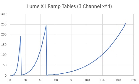
I tried different polynomials as well as exponentials but I found x^4 to work visually well.
For the 'Ultra-dynamic-range', it's exactly as thefreeman described, but instead of two, I used three different sense resistors each, each 2 orders of magnitude different. The key is to use a carefully chosen N-FET for the lowest sense resistor (highest current) since I take the R_ds_on of that Mosfet into consideration for the sensed current. Instead of focusing on the lowest R_ds_on, I picked one which is the most consistent at the driven gate voltage. I also played around with switching the reference voltages for the internal DAC to achieve more dynamic range too. Another note is that the DAC output is not quite rail-to-rail so you need to take into account for the lowest output voltage of internal DAC for the lower voltage ranges.
I removed the external temperature sensor since the 1616 seems to have a more accurate factory-calibrated internal sensor which the previous MCUs did not have to the same degree (though I can't find any manufacturer data of the exact accuracy tolerance). I'd also recommend ensuring the MCU has a good thermal path so the sensed temperature is accurate. Remember to disable the temperature re-write during Anduril's factory reset.
Due to the fact that the system now uses a higher current sense voltage, the other important aspect (especially since I'm hoping to design a driver that is economical to produce as well), is to use a less precise op-amp, saving a fair bit of BOM cost. I chose the much cheaper MCP6V66 with excellent results, but I suppose most other similar ones will work as well.
I got a few questions on compensation - compensation for the TPS61288 regulator itself should be fairly simple (the datasheet provides a good way to calculate it), but the op-amp compensation is a little more tricky if you're optimizing for lowest noise, EMI, and stability at all expected inputs and output loads. This compensation depends on the exact parameters of your circuit so it doesn't really make sense to port from design to design (and especially for op-amps - esp. the GBW and how it is set up internally since a lot of the precision op-amps are choppers) since it is also partially layout dependent; I'd encourage you all to play around with different values. I build dev boards for all my driver designs to help with this.
For the Lume X1, I chose a 'conservative' 40-ishW output since I wanted the driver to perform at its expected output across the entire battery range (as opposed to claiming that it was a 50-60W driver, but only with a fully charged cell at ideal conditions). I could increase this a little if I had full reign with the flashlight design as well to optimize for larger passive and magnetics, and flashlight power path.
Since then, I've managed to design one to fit an Amutorch E3 with 3S output configuration, and overall performance is really nice (main limitation being the inductor, and I've adjusted the output to be lower as a result to prevent inductor saturation)! thefreeman, your copper ring design looks great; it's a nice way to fit in a larger inductor (I had to use a flatter, lower power one for the E3).
Finally, I don't have any real thoughts between the MP and TPS part, both seem to be decent, but I do prefer the TI part for its lower Rdson FETs and because I've had a good amount of experience with other TI parts and they control system seems really well designed. The MP part has a 'higher' current limit, but the real-life power limit is determined by maximum junction temperature, which is based on other aspects of the system. Note that MPS just released the MP3432, though it's unclear to me at first glance what the key differences are between the previous versions; most likely some adjustments to the control logic.
Keep up the great work everyone and looking forward to seeing what you all come up with until I have more time to get back to the flashlight projects!
Hi Loneoceans, thanks for passing by and the kind words
Yeah the DAC is nice, especially since it removes the need for the LDO (and consequently the battlevel divider) and the PWM RC filter.
But since I have no programming skills I could only design a driver working with what is currently supported by FSM/Anduril (PWM). Actually I needed to add support for turning on the FET at a ramp level, I sort of miraculously managed to do that, I still need to add a delay on the FET enable due to the RC filter needing some time to fall when switching to the higher range. In the next version I reluctantly added a capacitor to delay the FET in hardware in case I don’t manage to do it in software.
For strobe modes, it seems that only the party strobe has issues (I haven’t tested the slowed version), but personally I couldn’t care less about those modes. That said I still don’t see any 5kHz ripple on the waveform so I might try lower capacitance for the filter to make it faster.
I’m also guessing that it is possible to have lower power consumption from the MCU with the DAC compared to PWM ?
The disadvantages that I see are the 8 bit limit (not really a problem with 3 sense resistors, I really prefer to only use two though) and that there is only one DAC, for a dual LED channel driver we would have to use PWM.
So it means you added DAC support in FSM ? Could you share your branch ?
I’m still working on the ramp so thanks for that.
In the version I built the FET is driven by the MCU at 2.8V and at that voltage the Rdson is a bit too high (~4.2mΩ) and probably not very consistent between parts. In the next version I’m driving it with the regulator’s internal LDO (4.8V), I wasn’t sure if it would negatively interfere with the regulator or not but after testing it doesn’t seem to be the case. With this the Rdson is about 1.1~1.2mΩ and I hope will be much more consistent between parts.
In Mike C’s thread we also discussed about using a mux to remove the FET resistance from Rsense.
It is indeed cheaper, about half the cost of TLV333 and still with pretty good specs, good find
For the regulator I took the values from Webench, for the op-amp I used 1nF (instead of 470pF in my schematic), I bought an oscilloscope recently and it looks stable at any output, I still need to learn how to record transient with it.
I’ll try with different values and see what happens, but yeah I knew I should have made a dev board, swapping tiny components and adding mores with tiny wires was a bit tedious to say the least.
Yes I prefer that approach too.
The advantage that I see with the MP is the ultrasonic mode, no risk of audible noise and it prevents switching frequency going so low as to make the LED flicker at very low output. I had to put a resistor across the output to have a minimum load for preventing that low frequency, did you use a similar solution ?
That’s great, E3 is easily moddable and has good thermal dissipation for its size. Will it work with B35AM in 3P configuration if someone makes a 20mm triple MCPCB for it? Its R9080 version should be as efficient as LH351D CRI90 at ~1000 lumens, but with much higher turbo power.
Why are Anduril lights with constant current drivers so hard to find? Cost?
A “slowed down” 5ms on time for party strobe will still reach the desired effect of freezing motion. I use the Anduril party strobe and 5ms strobe on a non-Anduril flashlight for light painting photography.
First of all I'll say that while Andúril may sound cool to some, the name of a phantasy sword is not exactly a common way to name flashlight firmwares. This is just the way I see it, of course. Then…
Average Joe or average chinese seller or manufacturer's answer: What is Andúril?
(link from: ▶ Flashlights with BLF User Interfaces - Master List ◀)
After checking it out: Whoa! That software is fairly sophisticated/complicated. We'll pass…
Andúril is meant for ATtiny MCU's and “FET” drivers. ATtiny MCU's are not really that common for the aforementioned fellows. Then, “FET” drivers are unregulated, their brightness is adjusted using a PWM signal from the MCU. Regulated drivers adjust brightness changing a MOSFET gate drive voltage (for variable load regulated linear drivers, like the SST40 types from Convoy), or by adjusting a buck/boost or boost-buck switching engine output voltage somehow… from a sense voltage signal (in both cases).
What does this mean? Software porting and conversions. This costs money, particularly if whoever does the software screws up (like someone from the driver manufacturing company to which Convoy entrusts and makes requests, long ago with the 12-groups Biscotti clone firmware and the SST40 drivers which couldn't save the software settings). This lack of care in the software meant lots of losses due to recalled products. When you write software for devices which can't be upgraded easily (and even in this case if you ask me), it pays off to do it carefully, taking whatever required time, and ensuring perfection.
So cost is one factor, but also interest (or lack of thereof).
Thanks Barkuti. So I shouldn’t hold my breath waiting for these to hit the market.
Only premium components cost about 15$, no soft, no pcb design , no hand soldering … To sell cheap you have to order in factory like 1000 pcs or more. ;))
OK, so just no interest in regulated output designs?
I think you didn't formulated this question correctly, and so you may want to reformulate it.
In my opinion there's interest in regulated output designs. All regulated output designs ensure constant current output (and so PWM-less standard modes), for as long as the input requirements are met. A regulated output design ensures an led cannot receive overcurrent, even if emitter is low Vf, all current paths are optimized and battery resistance is low (high discharge batteries).
Current limits can also be raised for regulated drivers, particularly for linears or variable load drivers, by the way. This is done by modifying the sense resistor or sense resistor stack.
I was inferring from Quadrupel’s post that cost wasn’t the main hinderance thus leaving demand as the limiting factor.
It doesn’t have to be, some of Sofirn’s lights have it, and they don’t exactly break the bank.
But if you’ll recall this thread, when the SP32 evolved with a more usable, regulated driver, it lost some lumen bragging rights, and that’s a turn off for some, if not a lot, of people.
I don’t think Sofirn has any regulated Anduril models.
They don’t; was speaking of regulated lights in general.
And as explained above, Anduril isn’t really congruent with regulated drivers, at least without some work, and I don’t think what it brings necessarily justifies that sacrifice.
I don’t count myself among those calling for Anduril any and everywhere, because I do value regulation, and the two are at odds, at least in the marketplace.
Anduril doesn’t care about the type of driver as long as it accepts PWM or analog input.
Count me in as interested in regulation, and also in using a CPU with more code space than the small AVR’s, even if it adds some cost.
While not exactly related to this, I'll post here a message I submitted to ToyKeeper recently (≈2 days ago):
This passiveness could mean lack of interes, although I'll keep listening. :-)
I wanted to say this because among other things ToyKeeper created Andúril and many of these sophisticated firmwares. ;-)
Concerning moonlight modes, I'll share with you a nice idea.
As the technically inclined among you already now, the very low current required for moonlight modes usually causes some trouble with the either the low resolution of MCUs (mainly), sense amplifiers, low or super low sense voltages (which are a must for high power and efficient designs), switching noise… or a combination of any of these.
There's a cheap way to solve this despite using low resolution MCUs, at least for linear or variable load regulated drivers. This is to use an alternative output path, a resistor in parallel with the standard driver output, for a moonlight mode. This way, fully closing the MOSFET gate in regulated linear or variable load drivers would only allow the very low current of the resistor in parallel from input to output to go through. Since a “3V” led has ≈2.5V of Vf at super-low currents, it is easy to calculate a resistor for a regulated linear driver presuming ≈3.6V of input voltage. R = V / I, and so a moonlight mode resistor for, let's say, 100µA moonlight, would be Rmoon = (3.6V - 2.5V) / 0.0001A = 1.1V / 10−4 = 1.1V × 104 = 11kΩ. This moon mode would not be constant current, with moon current varying from 154.5̅4̅µA with 4.2V at the input, the no-load voltage of a fully charged li-ion battery, to 45.4̅5̅µA with 3V at the input, the no-load voltage of a technically depleted li-ion battery. But this is a minor complaint, imho. The moon current would be flowing at all times into the emitter.
Hope this is of service. O:)
Like you said it would be always on so I don’t like this idea, with a small FET an resistor you can add another low power channel on a linear/FET driver, dimmable with PWM but the output will vary with the input voltage, I don’t really like this either as you can’t make a smooth ramp all the way up this way, which is kind of the main feature of Anduril is it not ? Plus I’m more interested in DC-DC converters.
The dual sense resistor solution only needs a <50$c NFET (if there is full Anduril support, otherwise an hardware delay is needed adding some components).
Converting Convoy drivers to community firmware should be possible, for those that use uncompatible MCU (most of them), they could be replaced by a small 1616 on an adapter like Gchart has done for the SP10S, the drivers take a PWM signal in so no problem on that side. A e-switch solder pad could be added on this adapter to use Anduril. Though there might be some quirks there and there. Like on the XHP35 driver the Vbatt voltage divider is after the LDO so it can’t read the whole batt voltage range. Probably other weird stuff too that one might see by reverse engineering them.
Emisar (Linear+FET) and FF (buck+ FET) lights use CC drivers with Anduril firmware.
Cost ? Sure, especially for DC-DC converters, also 7135+ FET design are super cheap, super simple, barely any knowledge needed, hence why they are also popular within the community where Anduril originates from.
Power density : a FET driver can achieve ludicrous power in small size and lumens sell.
You’re underestimating the impact 15$ parts has on the manufacturer’s margins.
Also I want to point out that a buck driver doesn’t mean efficiency. I measured the efficiency of the Skillhunt H04 driver and got arround 80% in high (less than 1A), that’s bad, linear (in average) driver bad, it uses an asynchronous buck converter and probably cheapens out on components.
True, but sometimes there might be some quirks that needs some actions from the MCU in order to mitigate them, which are not supported in Anduril, more on that later.
(sorry for the lack of updates)
Oh! Well, concerning simple regulated linear drivers you could feed the moon resistor from an onboard LDO (3kΩ for a 2.8V LDO presuming a Vf of 2.5V), and switch it on/off with a tiny MOSFET. ;-)
For switching drivers the dual sense resistor is great, but there's a need to switch off the bigger conductance sense resistor efficiently.