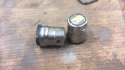
I just stripped a pair of 2 Cell, D Cell Original Manyfacturer LED Maglites… not LED Conversions
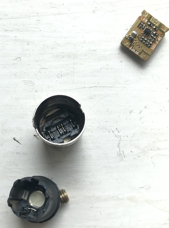
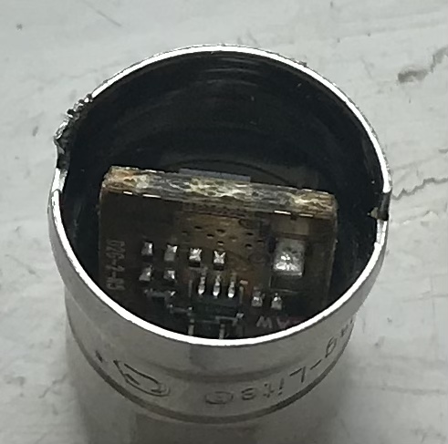
Stripping them down, the LED ‘unit’ is built in to the switch housing
The units are mini ‘drop-ins’ with an emitter on a seemingly immovable PCB with a driver board mounted internally.
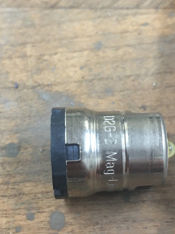
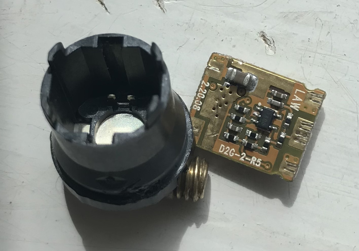
They are marked up ‘ Maglite D2G-2’
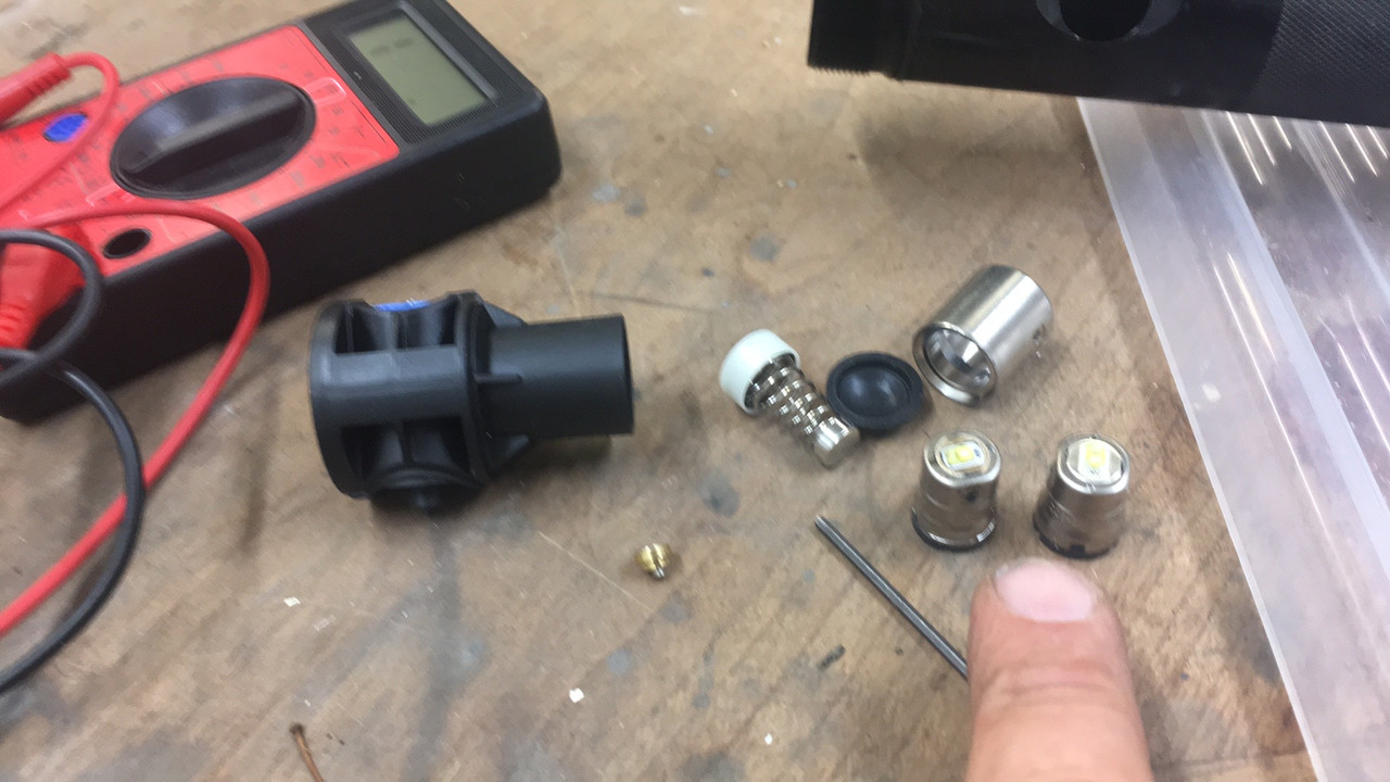
With a bit of prising, thx bottom plastic plug pops out, and the driver board slides out of two slots. No soldering of board to Emitter board, just press fit contacts
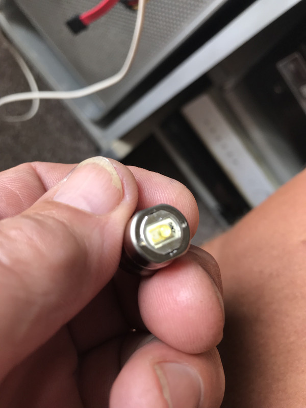
Getting it apart, I tested the LED and it works… so suspect the driver board
Did not get pics of the internals…
Only seen one other post on here from2028 asking about removal of LED PCB, from the housing, and it was not answered.
Google brings up zilch for D2G-2 as a part to buy…
Any one either modded one of these ‘drop-in’ LED units… or anyone manufacture a ready to go unit ?
I do not know…I actually took it on trust from the bloke that said they did not work that they did not.
I’l rig up a 3volt supply later to test then modules out. Should have done ti before really …but wanted to get them apart.
Switch module is different . I will get a few more picture later.
Yes true , no heats sinking. will get measurements …I probably have an order going in some times soon from Mountain electronics, so I am sure he will have similar to the fast tech one…
I initially did check the magnate website but could not find any suitable search box that searched Serial numbers for support…but I was on the old iPhone 5…small screen etc…
I do see the generic search box, which does not bring up any useful info.
Under support the only option I can find to enter the Serial number is the Register Your Product ’ page.
I left the lamps at the farm, so will need to go back to get the Serials…which is why I did nto post them in the original post…sorry…my bad…
I am just back from 4 week holiday in France…so chaos here as I get unpacked and sort my life out, getting back to normal…and the buggers that pay my salary expect more than just my bank details…they sort of expect me to turn up and do stuff for them too…so going to be tied up with that too
Thanks for following up with the pictures, that helps to see how it was assembled.
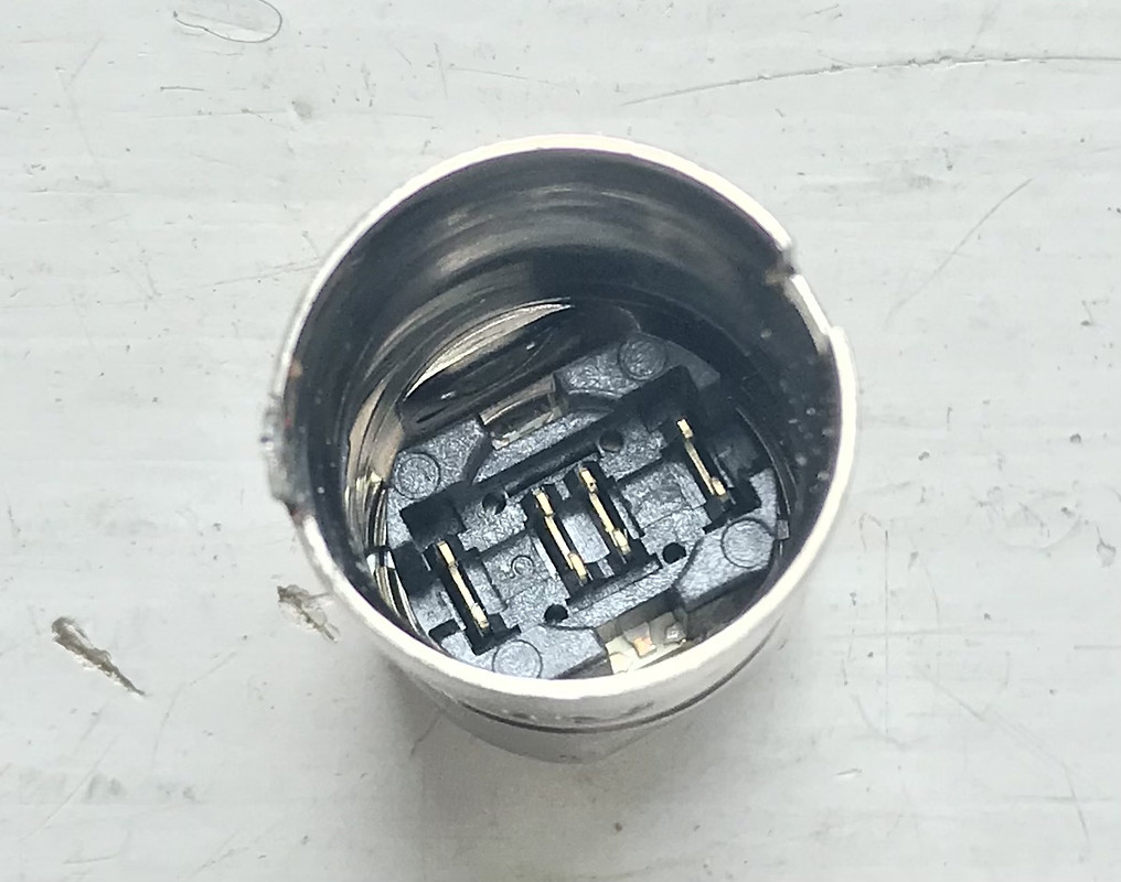
The two clips in the bottom black plastic piece—they both connect to the Positive terminal of the battery thru the switch?
And for the 4 clips at the top beneath the emitter, the center 2 apply power to the emitter and the outer 2 are connected to the steel case for the return path to the Negative of the battery?
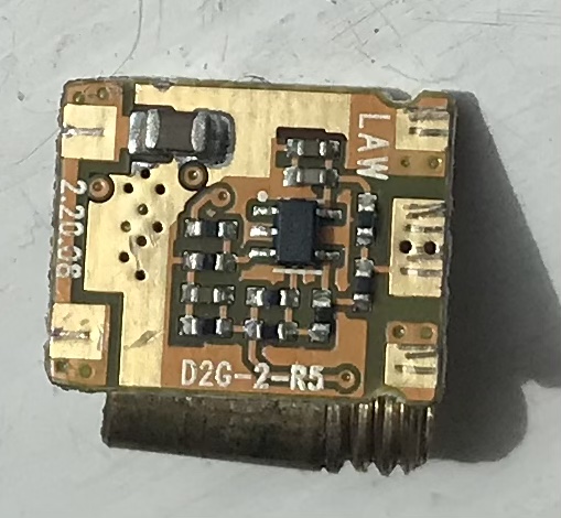
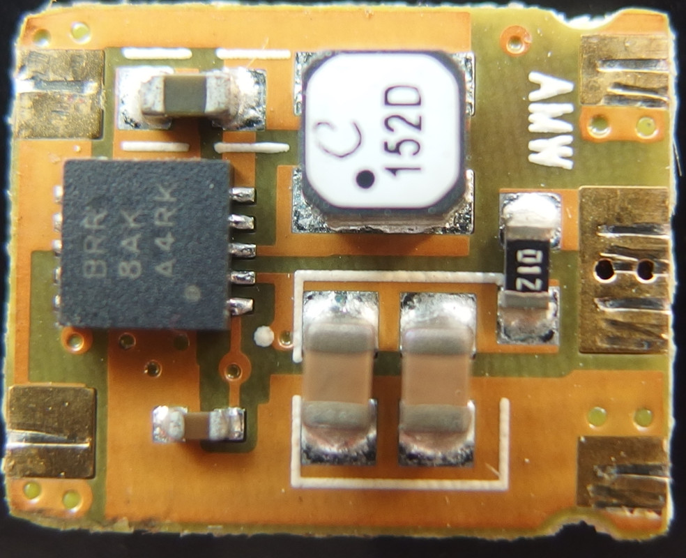
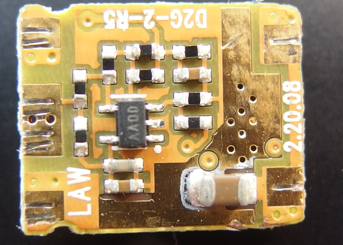
You wouldn’t happen to have written down the marking codes on the two chips?
Those are the best pics I took of the chips, so they are the only way to read what the markings are.
They were hand held pics from the iPhone though, cropped in.
If I break out the Canon 5D3, a tripod and macro lens I will try and get some better shots… time here is 2134, and I am off to bed. Depending on work tomorrow I’ll try and get better pics, to see if we can read the chip markings
I am afraid I could not get the second one apart, and once I realised it was actually still working too, I stopped trying to prise/in crimp the plastic base unit
I did get the two emitters mixed up, so not sure now which came from which
I know the earlier serial has the Allen Key fixing, and the later is the Torx, but got the emitter units mixed up.
I think I managed to find/ reproduce the fault that my mate had with them, which is why he thought they had died… End cap corrosion, simple as that. You’d think by now I’d have learnt to look for the simple things first… I was just too keen to see inside the LED drop-in’s !
I’ll get some macro pics of the emitters for you tomorrow, but don’t think I can get the other unit open without damage to it, or me stabbing myself with a prying tool !
corrosion on the end of the barrel/end cap can do that, these areas should be kept clean and lubed. if they do get corroded, the can be cleaned up with some fine steel wool or fine sand paper on a sanding block.
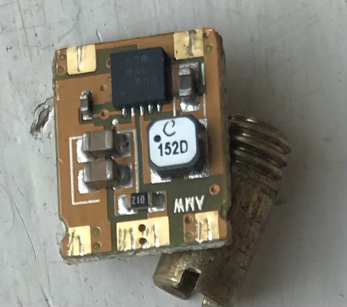
The big square VSON-10-pin chip looks to be a TPS61200, a switching dc-boost converter that can supply 300mA 3.3V up to 600 mA5V from 2 D cells. Don’t know what your voltage setting is since the resistors have no value marks.
The SOT23-5-pin chip marked “AA0D” wasn’t coming up from any search, but appears to be an op amp, assuming that the board is multi-layer with internal traces to connect some of the lonesome vias. Pins 3 and 4 are measuring the current from the voltage across the 0.1 Ohm sense resistor marked “01Z”. Pretty clever for 2008 technology.