Let’s talk about the Anduril patch you wanted: I can look at it tomorrow if that helps.
Is there really a need for a sense resistor for these low modes? I’m no hardware whiz but what about using a DAC pin to control a simple current amplifier, 1 transistor and 2 resistors back in the old days? I don’t know how it would be done now.
It would sure help yes
The other solution as mentionned in the first post is the mid ramp blink (BLINK_AT_RAMP_MIDDLE), but it doesn’t blink in stepped ramp (maybe it does if the step falls exactly on the blink ramp level?), so maybe modifiying the code so that it also blinks in stepped ramp is simpler comparing to adding a delay.
(Edit : although the the blink wouldn’t help in the case of the startup flash in the MP3431, as opposed to a delay)
Low modes can be done with a second channel, with a small NFET and a current limiting resistor, dimmed with PWM.
Pros : it’s simpler, about 50c cheaper.
Cons : output varies with battery voltage (not constant current), PWM.
Hmm, where does the cost saving come from? The 1616 already has several DACs but I’m sure there are issues I don’t understand. Avoiding PWM is really nice. It is ok if there is a little bit of nonlinearity in the amplifier and that the brightness varies slightly with battery voltage. The user can always adjust to their preference. We might want a logarithmic amplifier to widen dynamic range, since the dacs are just 8 bits. I don’t know how to implement that though.
Ok, I will look at the other thread and see if I can figure out what delay is needed, but I may still have a question or two.
Is there any software obstacle to using the DAC? I can ask ToyKeeper about it but I would have thought it was a fairly straightforward matter to configure the pin and read the voltage. I do remember something about it coming up before though.
Attiny1616 we have these microcontrollers available for purchase. Price $ 1 when buying from 70 pieces.
But I did not see any explanations about the firmware for this driver.
In the case of using a additional FET+resistor channel the HDR FET can be omitted, so it’s from that.
I don’t really understand how to make a amplifier circuit with just two resistors that will work in this case, but I’m not too knowledgeable about BJTs.
No idea, I know that Mike C used it in his firmware.
I’m not sure what to think of the DAC, it has some advantages but also inconvenients :
It doesn’t need to pass through a LPF contrary to the PWM signal, so that’s two passives less (one in the linear driver because it can use a combined voltage divider/LPF)
No problem with the flash since again : no LFP. The transition between the low and high current range can be mostly invisible since there is no need of a delay or blink.
It uses the internal reference so no need to supply the MCU with a fixed voltage. Although in the case of a dual sense resistor circuit, the HDR FET need to be driven at a fixed voltage to get a (relatively) constant RDSON, or it can be taken out of the equation by using a mux, but in the end might as well use a LDO instead.
Can lower the sytem clock speed to save power.
Cons
It’s limited to 8 bits, that makes the smooth ramp more coarse at the bottom of the high current range, as well a decreases the dimming ratio. Although Mike C, before using the dual sense resistor circuit, achieved more than 10bits by switching between the 0.55 Vref and 2.5 Vref (but I think he said that there were some issues with this ). Another solution is to use 3 senses resistors to compensate the lower resolution but I don’t really like this as it takes up more board area and it’s another signal trace to fit in.
There is only one output pin, even on the xx17s, although that’s okay with multiple sense resistor topology, it becomes a problem if there is multiple power channels like in a tint adjustable light.
I doubt people will buy 70 1616 for 1$ each to build a couple of drivers when they can wait a couple of weeks and buy them from digikey at 80c per quantity of one.
The transistor circuit would be an emitter follower aka common collector amplifier: Common collector - Wikipedia
The principle is that the base-to-emitter junction voltage is a standard diode drop (0.7v for silicon), and the transistor amplifies current: the collector to emitter current is a “constant” times the base-to-emitter current. The constant is called “beta” and it’s a parameter in the transistor data sheet. I put it in quotes because it’s not perfectly constant, but it’s close enough for our purposes. A small signal transistor might have beta of 50 or 100 or whatever. To get higher gain you’d use multiple stages, a so-called Darlington configuration. Anyway, I expect we’d use 1 transistor and 2 resistors (voltage divider) like in the diagram in the wiki article.
I’ve been chatting with TK about this, and she has some ideas for smoothing out the PWM, and I’ve also asked about the idea of using a programmable potentiometer (DS3502 or DS1841), I like that idea because it would allow putting the processor to sleep after setting the potentiometer, though the potentiometer itself consumes a little bit of power, 0.35mA in the DS1841 case apparently. That seems like a lot for a sublumen light that would send less power than that to the led, but it’s ok in the bigger scheme of things.
I know how to make a simple constant current sink but not sure how to make a voltage controled one (filtered PWM or DAC). Can you post a schematic ?
Those have a pretty large footprint, and expensive, although maybe there are smaller and cheaper ones.
The attiny1616 consumes <1.1mA at 2.5MHz with 2.8V VCC so that’s actually quite reasonable. A better power saving solution would need to be significantly better than that to be worth it.
I can try to post a schematic later today, will have to draw it and figure out how to upload it, etc. The circuit is pretty simple though. Imagine a PNP transistor. The emitter is connected to Vcc (the + power supply), the base is connected to one end of a resistor R, and the collector is connected to the LED. The other end of the resistor R goes to the DAC output.
Notice that the voltage at the transistor base is fixed, it is Vcc - (1 diode drop). The voltage at the other end of the resistor is also fixed, to whatever the DAC output is. So you know the voltage at both ends of the resistor, which means you can find the current through Ohm’s law. This current, multiplied by the transistor gain (beta), is the current going through the led. The value of beta is specific to the transistor and you would find it in the data sheet. Now that IC’s have made transistors “free”, I guess this stuff is now done with op amps, that are closer to ideal amplifiers without the weird nonlinearities and weird parameters. But I’ve mostly dealt with older stuff.
Does this make sense? It’s possible I’m somehow confused or missing something. There might also be some small filter caps needed to keep things from oscillating or whatever. I’m absolutely not expert at this stuff at all. I fooled around with these circuits as a kid but never studied EE or anything like that.
That’s a current source though, a current sink is needed since the anode of the LED is directly connected to the battery positive in this driver (or any NFET linear or direct drive driver).
Oh I didn’t understand that. You mean the led cathode is not grounded? Ok, do a similar circuit on the other side of the led, except use an NPN transistor so the emitter is grounded.
Is this the light main led? I think for a moon mode it is ok to use a small aux led, maybe a little SMT led. Then you can choose what it is connected to.
I do worry about the 0.6v PN drop of a silicon transistor, if VCC gets as low as 3.2 volts from a single lithium ion cell. There might not be enough left to light the led, whose Vf might be 3 volts or so. I don’t know if it’s sane to use a germanium transistor for this (0.3v drop instead of 0.6v). Maybe the whole idea fails because of this, and it’s better to use FETs somehow. This is an analog engineering problem though: maybe there are some experts around? Is Tom C here?
Yes, making a driver with grounded LED cathode is more complicated (although I have done it with boost topology) and in the case of a linear driver the FET would have to be a P-channel, I doubt they can handle this sort of load.
Yes I think that’s going to be a problem.
Anyhow I like the dual sense resistor solution because it gives precise current control, you know exactly what current a certain ramp level gives. In terms of components counts it’s only 2 resistors and a low resistance NFET (to have minimal influence on the total Rsense), and the gate resistor could possibly be omitted, normally we’re supposed to have one to limit the switching current in the MCU’s pin, but it is sometimes omitted (Zebralight don’t use any), plus here there is no repetitive switching (PWM).
In the future, for say 3~4A max drivers the 3333 footprint HDR FET could be replaced with a 2020 one, that one when it will be available (it was supposed to be available soon but the expected date was pushed back to 2022, not surprising with the ongoing shortages). Current 2020 NFET have a RDSON a little bit too high to use them to switch between the high and low current Rsense, that is when using a low Vsense value (Zebralight uses 2020 FETs and uses a higher Vsense to compensate, which has an efficiency cost). It’s also cheaper.
They are very easy to program, you basically send an address and a 24(?_ bit RGB value to the led by SPI. You can do that with two gpio pins and software, or maybe the chip has hardware for it. It is a tiny part (2x2mm), it has the nice bonus of being RGB, and you can connect as many as you want to the same two SPI pins and control them independently of each other.
What I don’t know is whether their lowest setting is dim enough to satisfy the moon mode fans here. I don’t have any of the 2020 ones but I have a 5050 one that I can try it with.
By the way I found some interesting data about the brightness of glow markers, which tells us something about the desired brightness of a super low moon mode. Here is a pic that ToyKeeper took of a 1mm wide tritium marker vs a Jetbeam RRT-01 turned up a few notches from its minimum level (the trit marker is much brighter):
Then at Light Source | BETA Light it describes that the brightness of glow tubes is measured in microlamberts. I couldn’t find a brightness spec for those tiny marker tubes, but Betalight Torch | BETA Light mentions that their map-reading torch has 1000 microlamberts.
I was unfamiliar with this way of measuring brightness so feel free to check my math. But, from what I can tell, lamberts and microlamberts measure surface brightness: 1 lambert = 1 candela per cm*2. For the 1mm*3mm tube you’re effectively seeing a surface area of 0.03 cm*2, so at 1000 microlambert the light coming out is 3e-2*1e-3 = 3e-5 candela. If that is focused into 1 steradian facing the camera, it would mean a green trit tube that size produces 3e-5 lumens. According to one of the charts (the little clickable image) on mixglo, blue phosphor is about 15% as bright as green, so we’re looking at 4.5e-6 lumens. If the led Vf is 3 volts and its brightness is 100 lumens per watt (333 lumens per amp), we want about 4.5e-6/333 = 1.35e-8 amps=.0135 microamps to the led, to equal the trit tube.
Does that sound even slightly plausible? It means connecting the led to a 5v USB brick with a series resistor (2 volt drop across the resistor), the resistor would be 2/1.35e-8 = 148 megohms. I don’t know if normal resistors that high even exist, or if my DMM reaches such a scale. Potentiometers on digikey only go up to 5 megohms. I guess it is possible to use 5M or 10M and further dim by PWM but wow. So I have to wonder what is going on with that Jetbeam light.
That sounds too low to me, I mean I don’t have any tritium tubes to compare directly, but from what I remember when I saw a watch with tritium hands, it wasn’t too different from what I get at 5uA, I could very well remember wrong though. (Edit : I probably do)
Anyhow 5uA is already too low for me, I’ll probably use 50~100uA, the goal was the moonlight level of Zebralight H/SC600 mkII which is 100uA (with 3V LED), so that is achieved. (With the main LED, because most hosts don’t have room for aux LEDs, so while the digitally controlled LED you linked sounds interesting, it’s doesn’t satisfy my specs).
Aside from that I modified the value for R6, at first I tried with 1k, which worked down to 1/1023, but since there was less ringing during transients in simulations with 10k(same as KR4 driver) I changed it to that, without enough testing after that… and it doesn’t works properly, on the 1st and 2nd PWM the LED doesn’t even lit up, on the 3rd the current is about 5uA (should be 15), and with a slow start, similar to the KR4 driver. I changed it back to 1k and get 5uA at 1/1023 (well 6uA in reality but close enough ) , 10, 15uA…etc on next levels, as expected.
Ringing if it happens (haven’t checked yet) would be only during transients and for a very short time, as in 1ms, nothing visible, steady state is stable. Increasing C4 to 4.7~10n would probably help, though I’m not sure that’s really necessary.
I just wanted to make a comment about how great it is that you were able to create and share this design. I hope some others are able to put it to use.
I’ve never tried building a driver, and I’m not sure if there is a good way to manage the components on the backside without a hot air station. However, since I have an original D4 would benefit from an upgrade, if I had the time to try, this seems like a good candidate.
The flash you mentioned, is that a behavior related to not knowing the proper initial control value when moving between channels? Does it flash low or high, or does it depend on the direction being ramped?
The D4 driver is probably the same size as the D4v2 (22mm) so yes that’s a good candidate.
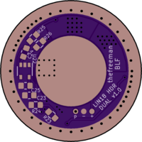
The 0603 sized components on the back (C6, R10, D1) can be hand soldered, I solder SMD components down to 0402 (never tried smaller) like shown in this video , for just 3 components it would probably take a longer time to use hot air anyway.
The most difficult part is the Attiny1616, I reuse a stencil to apply paste just for that part, as buying a new stencils for each drivers would be a bit expensive for me since I do a lot of prototyping.
For the rest of the components I dispense the paste manually.
For manual dispensing I highly recommend to not use big syringe the paste usually comes in, the control is very bad (not enough/too much pressure) instead I use a 1mL syringe with a 25 gauge (red) plastic tip (less resistance than metal tips)
You can buy stencils from OSH stencil after completing the OSH Park order.
It is also possible to reflow the components without using paste and stencils by pre-tinning the pads with solder, clean, re-apply flux, place the components, then reflow on a hot plate. A few pads might not wet properly but that is solved by poking the components a bit during reflow. I used this technique one time with 0402s, SC-70 and a small QFN.
I did reflow two times a 1616 by manually dispensing paste, the first time I put a bit too much paste and couldn’t see if it was properly centered, had to reflow a second time to center it properly, and then clean the solder bridges by draging the iron tip along the pads ( like this ). The second time I put less paste but still had to correct solder bridges. I’m using BiSnAg though and with SnPb it might work better because it flows much better. Only pasting the thermal pad and manually soldering the side pads could also be a solution.
Here is a more technical explanation of the driver and what causes the flash.
To use a car analogy, 1st gear is slow speed, 2nd gear is high speed.
Speed at max throttle on 1st gear = speed at min throttle on 2nd gear.
So you get a nice big speed range by pushing the throttle on the first gear, then instantly throttling down and changing to the 2nd gear, then progressively throttling up again up to max speed.
Except, your brain might tell your foot to throttle down when going to the 2nd gear, but your foot can’t do it instantly (PWM RC filter), so for a moment (~5ms), you’re at full throttle and already on second gear, which on a car would mean a stall, but on the flashlight it goes full output, and that’s quite undesirable.
It only does that when ramping up, when ramping down the throttle is already at minimum before switching to the 1st gear.
A solution is to wait a bit to change gear (HDR FET delay, either hardware with the back components, or software, which I don’t have the skills to implement). Another one is to turn off the transmission for a moment, like a clutch does. (mid ramp blink function, but that only works in smooth ramp mode)
To clarify, there is only one channel, this is different to the multi power channel drivers that use 7135/linear FET and DD FET channels. Again kind of like a car, there is only one engine, the whole speed range is achieved with multiple gears. On a linear driver like this one I could have used multiple channels, on a boost or buck driver through that would be much more complicated and the one engine/multiple gears solution makes much more sense. Here I applied it to a linear driver because IMO it still is a slightly better solution even in that case.
Digikey has the Attiny1616-MNR back in stock.
Availabily of DMN22M5UFG has been pushed back to 2022 so I added SISS80DN as alternative, RDSON will probably be about 2.5mΩ, 0.5mΩ more than DMN22M5UFG which need to be taken into account for the HI-Rsense. I might order some with my next order and test it.
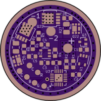
It has HDR functionality but Anduril isn’t compatible with it for tint ramping, thus no low moonlight. Q2/Q22 and R8/R28 should be left unpopulated and Q2/Q22 shorted.
R1, R2, C1, C2, Q3, U1, U3 are in single quantity, the rest are doubled (R3=R23 …etc)
LFPAK33 FET for Q1/Q21
0805 size for R7/R27