There is a very good writeup of the AVR-1 series here, with links to some dev boards on Tindie:
The page is not new, but I just found out about it. I might order one of the Tindie boards to attempt some software hacking.
There is a very good writeup of the AVR-1 series here, with links to some dev boards on Tindie:
The page is not new, but I just found out about it. I might order one of the Tindie boards to attempt some software hacking.
Oh this is interesting, there is also a new “DX core” line, a follow-on to the old MegaAVR. Most have high pin counts but of flashlight interest is the “DD” series, which will have as few as 14 pins (SOIC only). The 20 pin version will be available in 4x4mm VQFN:
https://www.microchip.com/en-us/product/AVR64DD32
They will have up to 64k program flash, 8k ram, and a bunch of new analog capabilities not seen in the Tiny series. Writeup here:
Microchip also posted and deleted a document about an AVR-DU series that is probably a ways off, that will have USB on the chip. The document is preserved here:
https://github.com/SpenceKonde/DxCore/files/7041383/AVR-DU-Product-Brief-DS40002328.pdf
14 and 20 pin versions SOIC only but there will be a 4x4mm 28 pin VQFN.
I think in the long run we will want USB in our flashlights (lots already have USB charging). It will make configuration a lot easier than 15 clicks this, 7 clicks that. We can do it with the AVRISP or UPDI wires now, but that takes comparatively special hardware vs. a common USB cable.
I was thinking that with 12 bits ADC, Vsense could be read by the MCU and the current regulation done with a PID algorithm, like it is done in the YLP Unicorn 1.0 or gekko, which decreases components count a lot, but the min Vref is 2V of those so in the end it’s not more precise than 8 bits with 0.55V Vref…
The 10 bits DAC could be used instead of 10 bits PWM in CC drivers.
USB communication with would certainly be nice if you could load a config file instead of having to compile and flash.
Spencer Konde’s document mentions differential ADC in some of the 2-series parts, and also increasing ADC resolution by oversampling. Could any of that help?
I have another crazy idea for getting data into the light, for stuff like configs. It would be mostly for existing lights. The idea is replace the battery with a dummy one with wires coming out, so the power would actually come from outside. You’d need a tailcap with a hole to run the wires through. Then you could modulate the voltage (say between 3.5 and 4) to send data. Do you think this could work? Any idea what speed it could run at? That is, would the MCU get confused if its Vcc changed too quickly?
Even if it were only a few bits/sec, that would be more convenient for loading a config than all that clicking. It would be great if it could reach the kilobit range, allowing uploading a complete firmware build in reasonable time. It would not have to run the main flashlight led, so only a few milliamps would be needed. So it could be run by an MCU with a DAC output and a small amplifier, powered by USB.
I’ve wondered what it would take to just use the MCU for a linear driver instead an op-amp. I know even the brand-new 2-Series has improved DAC and ADC. Shoot, it looks like Mouser even has the new attiny1626 in stock
Probably, maybe this is what Inferion ( Unicorn/Gekko driver designer) talks about here and other comments further down. This goes well above my head though.
The end result is a driver with very few components : a RPP PFET, the MCU (+ decoupling cap), a current sense resistor, a NFET and RC filter to drive the gate of the NFET with PWM, 7 components! Compare that the 17 components for the same functionality with by using an Op-amp (18 in the Noctigon KR4 driver).
Scratch that, the 2-Series does have a better ADC but they actually removed the DAC. Hmm, could probably still do with PWM through an RC filter.
I have some reading to do.
Also Microchip themselves has them in stock, little cheaper in shipping actually, least for me.: https://www.microchip.com/en-us/product/ATTINY1626
(ref: https://en.wikipedia.org/wiki/ATtiny_microcontroller_comparison_chart)
In the Unicorn they use PWM with an RC filter :
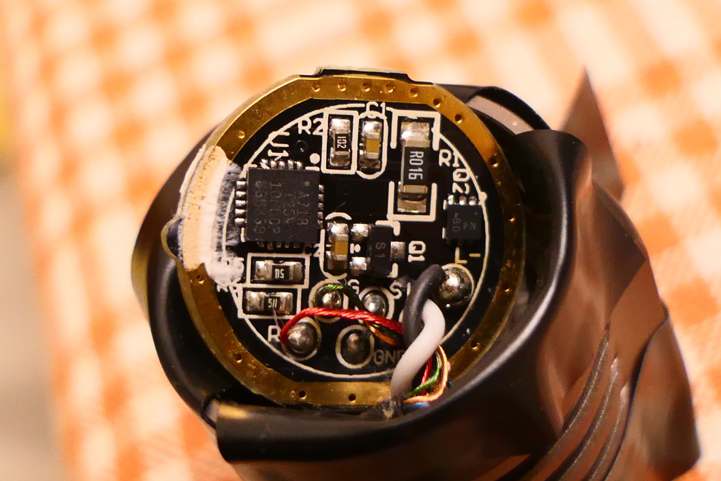
R2 and C1.
It’s possible that the resolution of the DAC would be insufficient anyway since a small difference of the drive voltage can result in a big resistance change of the FET.
Hmm, that’s with an attiny25. So clearly it’s feasible. Based on that article you linked to, he clearly has a lot of fancy math/firmware stuff going on. But I wonder if that can be simplified a bit (or made easier with the newer peripherals of the 1- or 2-Series).
The Unicorn goes from 2.7A to ~10.5mA (rated 850lm to 3lm), so about about 255:1 dimming range, with a 16mΩ shunt, Vsense= 43.2mV meaning that he manages to read 170uV with a 10bit ADC.
In the gekko he improved the dimming range, 900 to 1lm, probably 2.9~3A to 3mA, so about 1000:1, with a 10mΩ shunt, Vsense = 30mV down to 30uV!.
The board even says 5A-1mA, which would mean a even higher range : Обзор YLP Gekko 1.0 | Обзоры налобных фонарей
(There is one additional resistor and capacitor near the MCU, no idea what they are for).
So yeah, fancy maths indeed.
Edit : the resistor and cap are probably a low pass filter to generate noise via PWM for dithering as mentionned in this App note
There is also an App note about oversampling with Attiny0 and 1 series with example code.
Hi again, been on vacation in Switzerland climbing, cycling, hiking etc etc, and us usual my vacations are email and computer free… so a late reply as I’m catching up a bit.
I’ll just clarify this a little…
With the 3217 I ran it 3.33MHz, then when power off with clicky switch is detected I ran the periodic power on check interrupt by using the ULP (ultra low power) clock at 32.768kHz. With 125ms intervals I got plenty of time, around 10 seconds if I remember correctly. The problem I have with my 1616 driver is not changing the clock, it’s that when the clock switch is done the OTSM cap is drained to the point where detectable off time is too short for me to use (around 1 second). I couldn’t solve it out so I just went with ULP clock all the time. Issues with slow ramping have been sorted so I don’t really have any reason to use any other clock than the ULP now.
With all of this said it could very well be a driver design issue. I’ve only used the 1616 with my boost driver which is 17mm. It’s the first driver that forced me off the larger 3217 due to space constraints. The boost driver has 2 x 68uF input caps and these of coarse have to be depleted before the pin interrupt can detect power off, which in turn can mess a bit with remaining capacity on the OTSM cap once the pin interrupt triggers. Instead of figuring it out completely I just went with ULP all the time as it appears to buy me enough time to use OTSM as intended with my current boost driver design.
Thanks for the clarification.
BTW Digikey just received new stock of Attiny1616-MNR , currently has 1780 in stock.
What is the advantage of OTSM (leaving the MCU powered by a capacitor while the battery is disconnected) instead of OTC? OTC would seem to use smaller parts. Just wondering.
With OTSM you actually keep track of time and can say with certainty “the light was off for 0.73 seconds”. With an OTC you’re just taking a measurement of the capacitor which is fairly imprecise and will change depending on whether the light is hot or cold.
In addition to what gchart wrote, you get different readings depending on the battery voltage with OTC. If light temperature and the actual off time are both exactly the same you will get a different reading if battery voltage is 4.2V compared to if was 3.5V. If you only have a single type of off press in the firmware, not short off and long off doing different things, then OTC is reliable, tried and tested. I have short and long presses in my firmware, OTC is not consistent enough for that.
I find an old posting I made about the subject: Texas Avenger "TA" Driver series - Triple channel + Bistro or Narsil + Clicky or E-switch - The Ultimate open source driver! - #1389 by Mike_C
Thanks, that was interesting, I didn’t realize that the capacitors were that unstable with temperature and (apparently, from the linked thread Off-Time Memory Dependent On Altitude? - Resolved! ) with air pressure. There are stable types of capacitors but I guess they are bigger. I’d hope that resistors are pretty stable either way. You can measure the battery voltage to calculate the RC timing if R and C are known, and you can measure the temperature too, but maybe the capacitance change with temperature is not predictable enough to calculate. It’s still interesting to hear that OTC ends up being too imprecise to distinguish a short from a long button press.
Do you mean you use ULP (32khz clock) literally all the time, and the Anduril UI still works? Is there a reasonable way to switch out of ULP at least some of the time, when more CPU is needed?
There are more stable capacitors yes, X8L for example : 3% max change over 60°C. Though they still have initial tolerance, I see them at 10% from what Mouser has. Plus the DC bias, but that depends what value is needed. I suppose that battery voltage is something that could be accounted for since it’s known ?
Mike writes his own firmware.
IIRC the avr-1 has an internal RC clock that is calibrated at the factory. It’s still nowhere near as accurate as a crystal, but maybe it could be used to measure the OTC capacitance by timing the recharge when the light is turned on. Is accuracy better than 10% really needed to distinguish between a short and long press anyway? I’d expect short press < 150ms, long > 300ms, or something like that, where it’s ok for in-between measurements to not be definite. So 10% either way won’t matter.
I wonder if it’s possible to use the serial port as an accurate timebase to calibrate the other stuff while the chip is being flashed, since the baud rate will derive from a crystal clock in the USB gizmo. Maybe that gets too fancy if it is even doable, though. I’m presuming that putting an xtal onto the driver itself is not really feasible. It would be nice for some things, like turning on the light at a certain time of day. People do keep asking for that.
I use ULP all the time but with my own firmware, never tried Anduril. Switching clock is easy, not and issue for me unless I’m doing it during off press. So far I have not needed to switch clock from ULP but my firmware isn’t complete yet.
No, it won’t matter but I don’t really care, OTSM works fine for me so I personally couldn’t be bothered with all the above.