As I said, I may have had that backwards. D1 definitely had a bad beam, and I remember some folks swapping reflectors between D1s and GT mini. I can’t remember which was better and never had either personally.
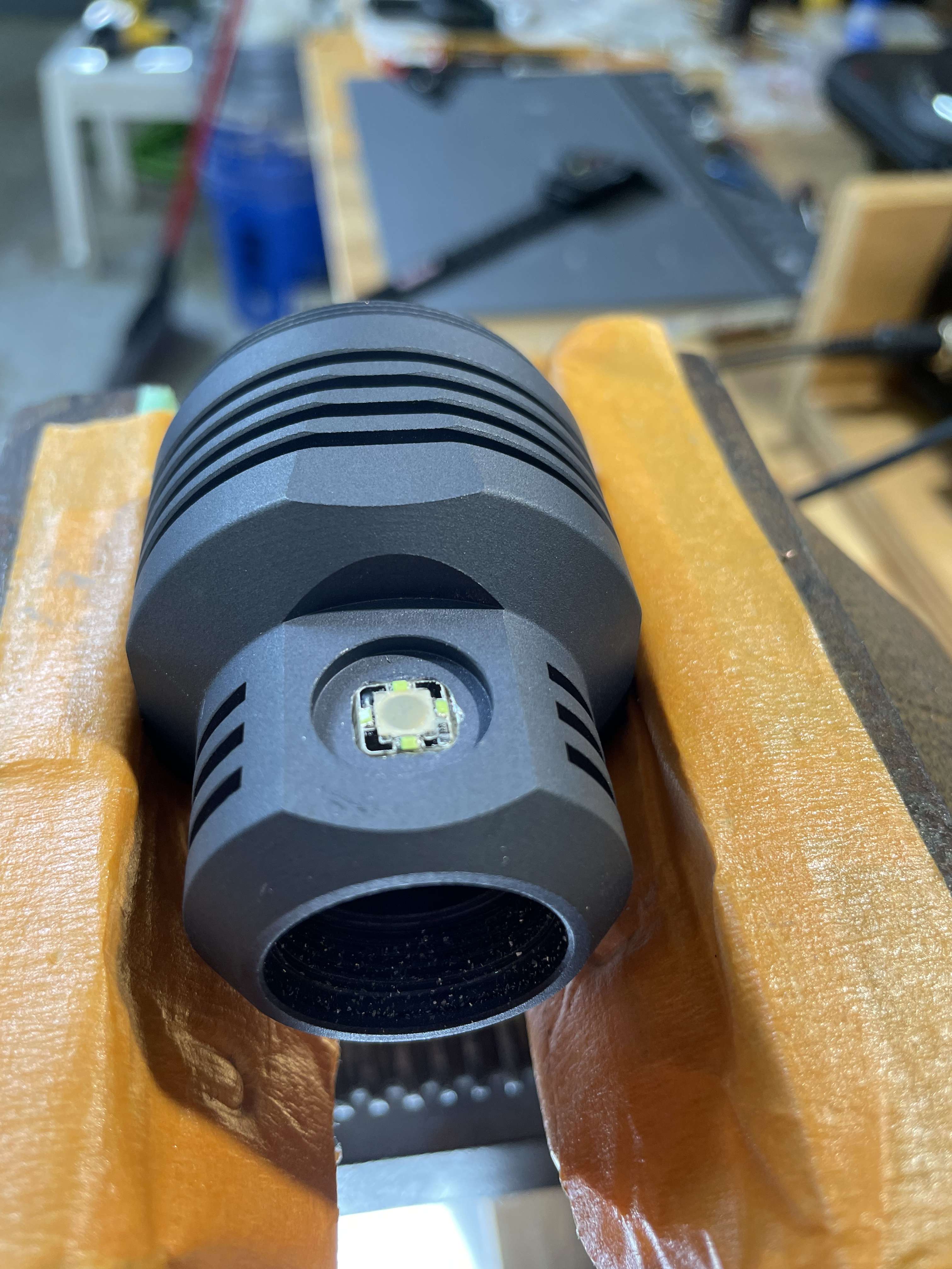
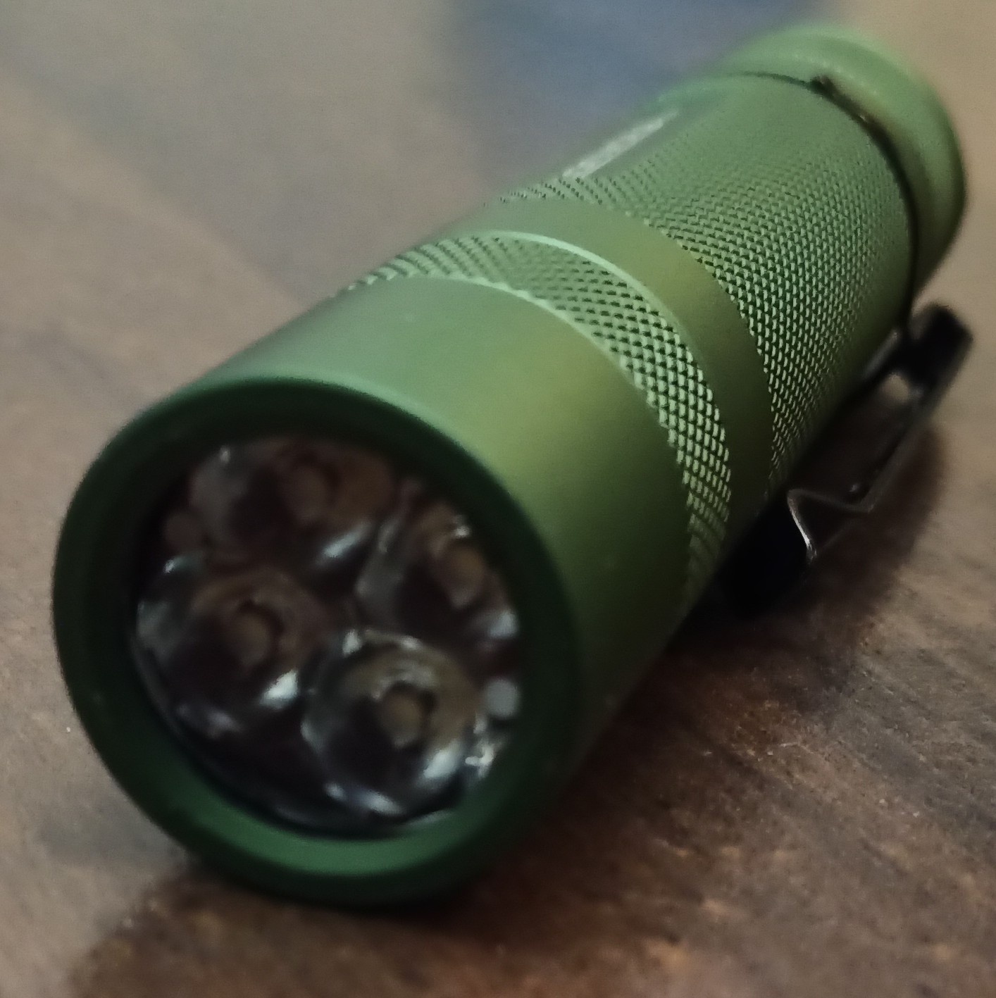
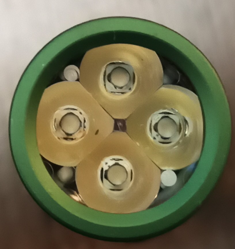
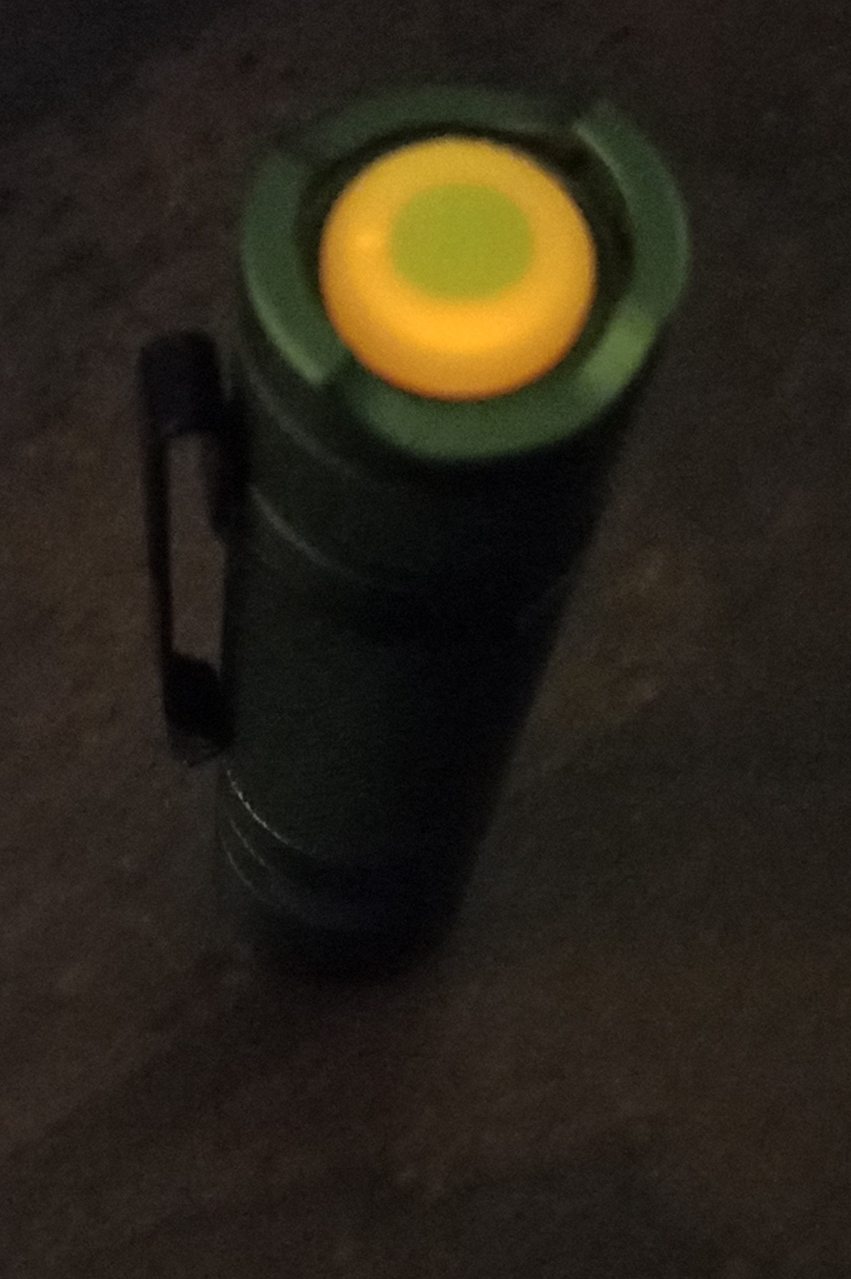
Got a cheap triple flashlight from Alonefire. It comes with a white, warm, and UV LED. Swapped out the random white and warm LEDs with a XPL-HI 5000k and a sliced LH351D 2700k. Apologies since I can’t really manipulate white balance properly. The LH351D looks more orange IRL rather than rosy.


Sunwayman V11r
LH351D 2700k sliced dome
 .
.
low 0.02 lumens
Turbo 335 lumens
repacked control ring w Nyogel 767a
 .
.
 .
.
unfortunately the beam is unacceptable due to a dark shadow in the spill (this does not happen with dome on)
===
redid the reflow to an LH351d 2700k with stock dome on
 .
.
low 0.03 lumens
Turbo 425 lumens
the beam is Much better!:
 .
.
 .
.
So far, i got the xhp35 HI 4000k in the M2r warrior, and i got the D1s done! 3.5 hours later! heres some pics. sorry for the link, dont have time to upload pics, but wanted to share!
Highlights:
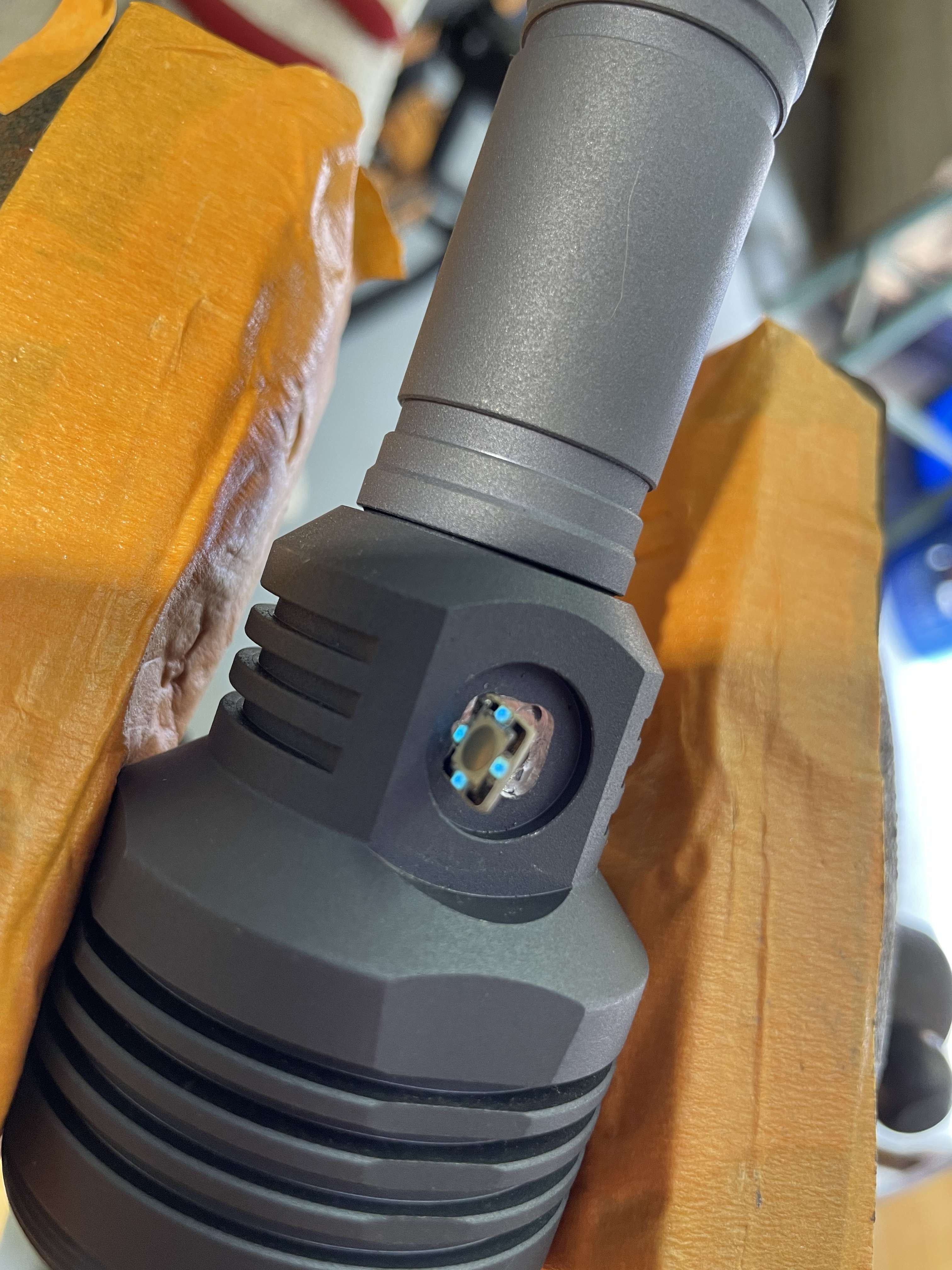
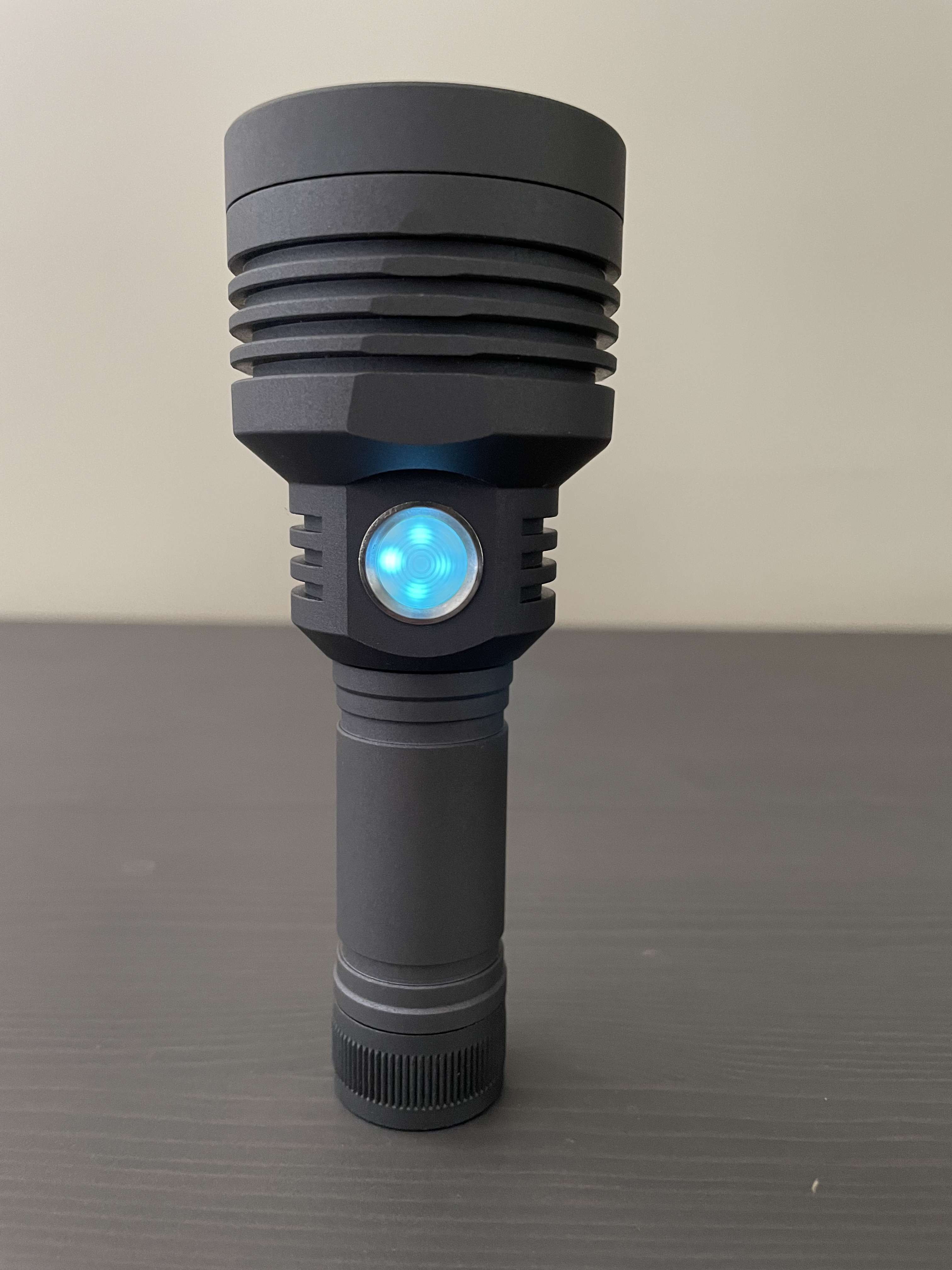
Emisar D1s
7.5amp KR4 driver, Anduril 1
Lighted Cyan Switch
SFT40 LED (still needs to be tuned properly, height adjustments)

That D1s looks awesome Artiet!
I removed the spacers from the GT4 battery carrier so non-nipple button tops can fit.
Thanks Yokiamy!
Artie, D1 beam shots ASAP Please! looks like your a Surgeon with that dremel too
Artie, where did you get the side switch, I need one for a MT07.
And could you explain what beam appearance you are looking for when tuning ?
Got several lights that need tuning, never knew how.
.
Nice mods ![]()
I did not know the SFT 40 could handle 7.5 amps, wow ![]() You are giving me ideas
You are giving me ideas ![]()
.
Looking good.
thank you! And JaredM for this info! Of course I already installed everything and before I came back to look at these comments.. but I still have the second driver for the D1 to try this with. Thank you!
even with the xpl-hi the beam was nasty. It's interesting because I see all of these posts about simons osram lights lately with people complaining about the beams, one of the biggest reasons I even figured I would switch the leds out during the d1 & D1s driver swaps was because the beams were already so poor anyway, just fuzziness around the hotspot, not impressive for what I come to expect from Hank. I would love to have a convoy sft40 quality beam on my d1s right about now! I know Hank didn't design this reflector for this led or even this size led.
I put a kr1 reflector in the d1s a while back and it improved it greatly! The kr1 reflector has made every emitter I've used it in (over a dozen) look really good! It's one of the best all around reflector I have ever used.
the d1s reflector- I wouldn't be surprised if you had it correct JaredM, and that it was flawed. I'm going to work on getting a gt mini reflector as when I had one of those i remember the beam was nice, maybe I'm wrong. but worth a try. I found a very similarly sized reflector on kaidoman, but it had a slight op which was disappointing..
Tmaxxjj - I have a lux meter for measuring throw.
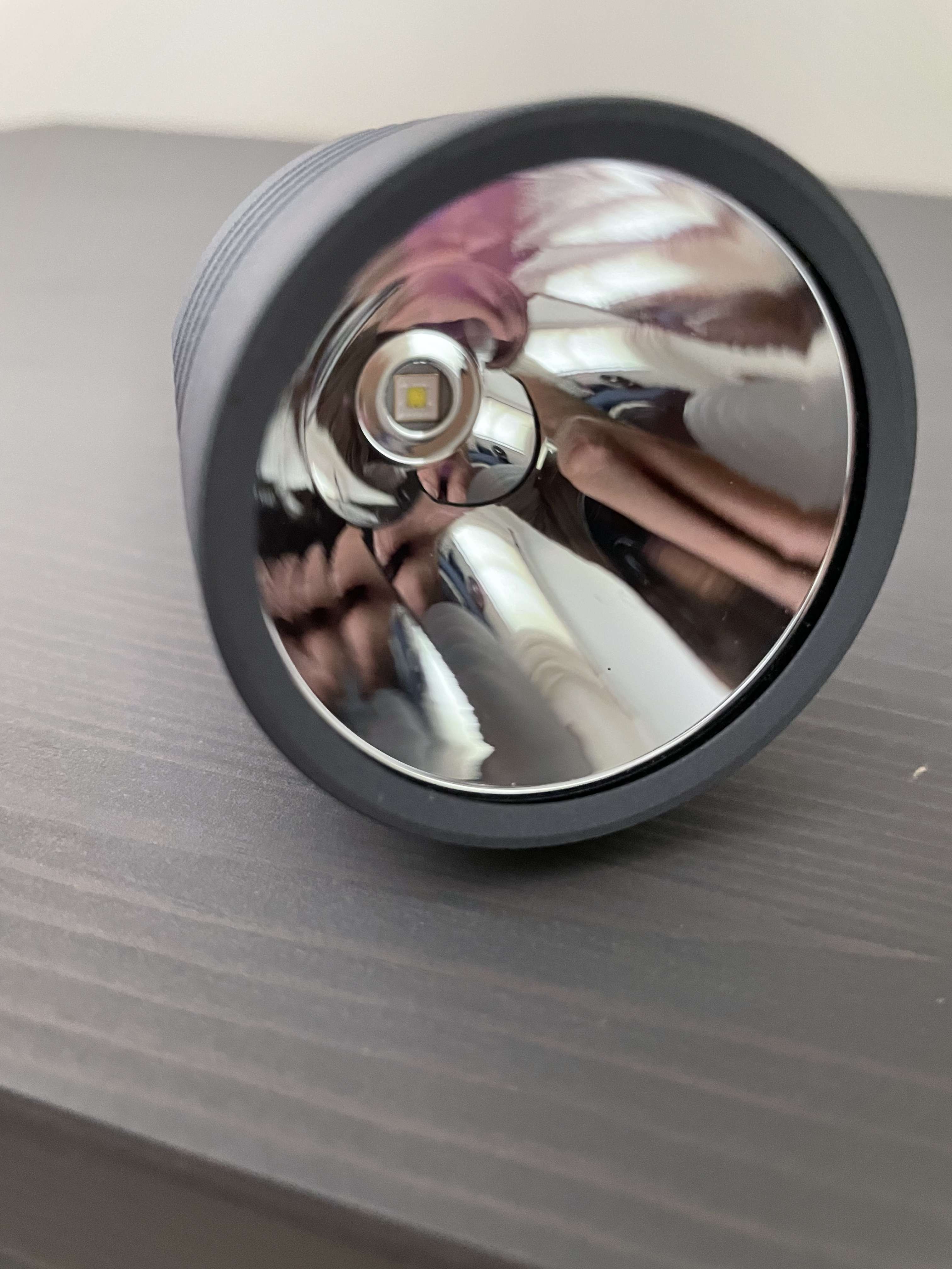
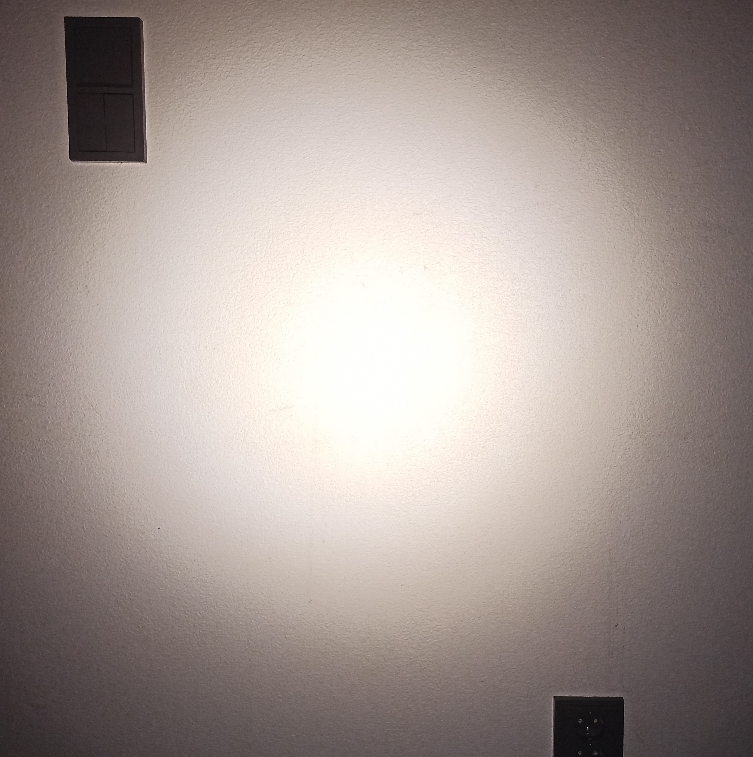
when I say tune the beam (I am probably saying it wrong), I mean to eliminate the rings and artifacts, not optimize the throw Perse, although I feel they're probably hand in hand to an extent. I just want it to look better than this picture below.. it's very aggravating. The reflector is very thick at its emitter opening, and also wide. And with a small mcpcb it makes the options you have for lowering it without hitting the +/- terminals very difficult. If I had a lathe, this thing would already be either fixed or destroyed!
what are you implying/asking tmaxxjj? To measure while adjusting to see what works better? I'm using my eyes to determine the beam has terrible rings in it, yes. I don't need equipment for that lol. I don't care about total throw so much, I've recently felt like it is whatever the battery, led, and driver will let it be (total Lm & cd). I am way more concerned about how the beam looks. It's kind of all that matters, within reason.
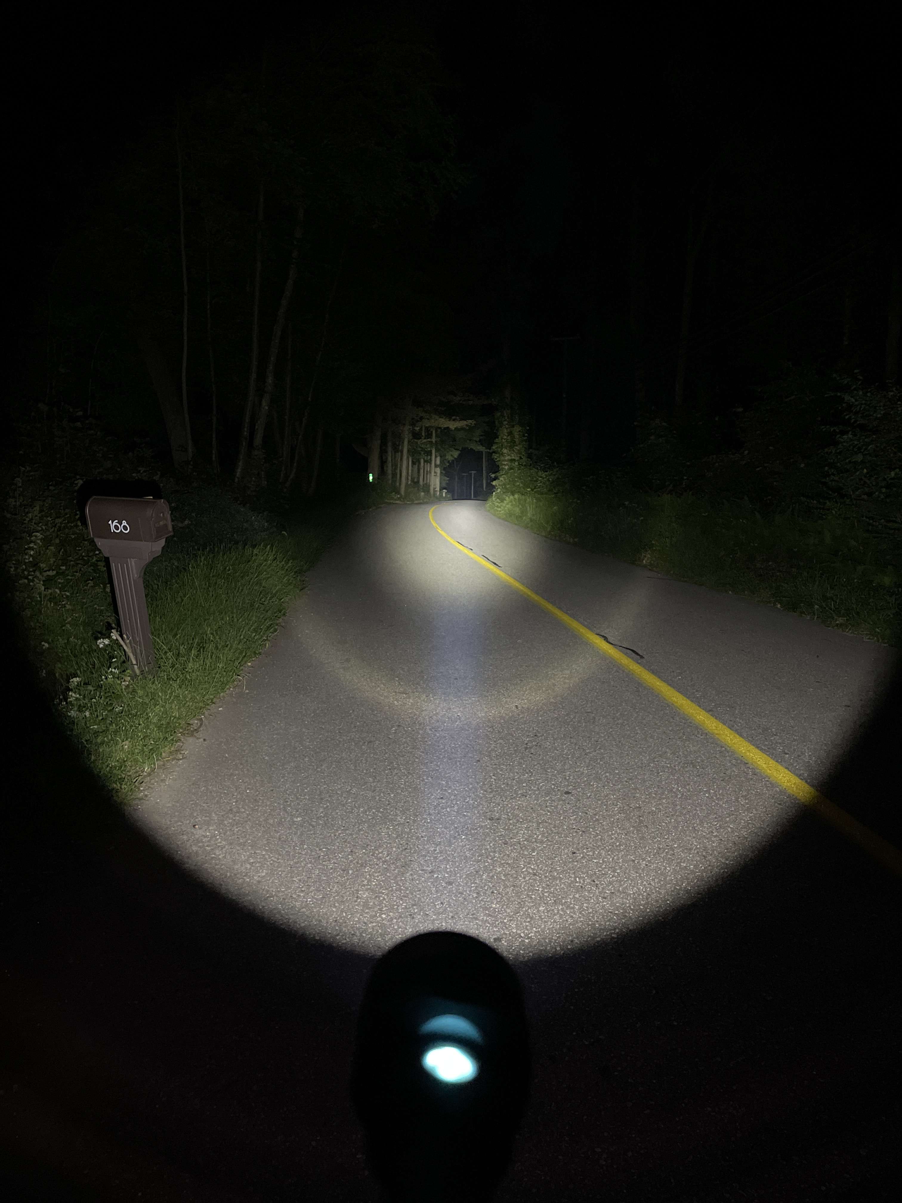
D1s with a well fitting centering ring and the sft40 led.NOTE: the led is sits VERY low in the reflector open8ng with this centering ring, without the centering ring it's better than this pic but still not good by any means. I'm going to start reaming until someth8ng happens, good or bad. I've reamed before so I have experience of how not to mess that up. The beam on the other hand, who knows...
Today I finally built Convoy S21A quad using LD-A4 driver, Nichia 219b’s from Convoy flashlight store, lighted tailswitch and Kaidomain quad mcpcb and tir with self made spacer. Driver runs at 10A and leds are mix of 4500K and 3500K. Spacer is ~22mmx5mm copper piece with small machined groove for pcb. Kaidomain quad tir fits S21A perfectly.
Beamshot from 1,5m distance with color balance of 4600K
Cool :sunglasses:
I guess it will run hot AF, no? :smiling_imp:
I’m guessing you must have had a bad one. My D1S’s beam and focus is just perfect. Even with its age it’s still one of my favourite torches, and with them being discontinued they’re very sort after.
To tune the reflector means to get the best focus and thus in turn optimal throw, so that’s where the meter would come in. But as you say, you’re just looking for a pleasant beam that looks good. Which is fair enough!
Once you’ve finished and you’re happy, I’d still be very interested as to what numbers you’re getting from it with the SFT40 ![]()
Not much different compared to S2+ triples that use Fet-driver.
Kapton tape on the bottom side. Hot air (low volume) on top/sides with flux paste around the LED to help liquify solder.
To put new component on you will want to clean the pads very well and use more flux between LED and pad combined with the smallest possible amount of lead free solder paste.
Kapton tape shouldn’t be needed, I reflow double sided PCB and back side components falling off hasn’t happened to me (yet at least).
How powerfull are those aux channel LEDs ? Likely low power I guess, maybe soldering the thermal pad is not necessary. Do the anode and cathode pads extend past the footprint ? (Usually for the solder to overflow) If so you could try soldering the pads by putting your iron with a solder blob there. For desoldering, take a knife and remove the dome and phosphor, then apply directly your iron on the led’s substrate.
Edit : they don’t

You could try scrapping the soldermask next to the pads so you can put your iron there.
Yeah I went for the same review for pictures.
So what I would do without hot air is desoldering as described in my previous comment, I’ve already done it that way, it works well (albeit with the led destroyed).
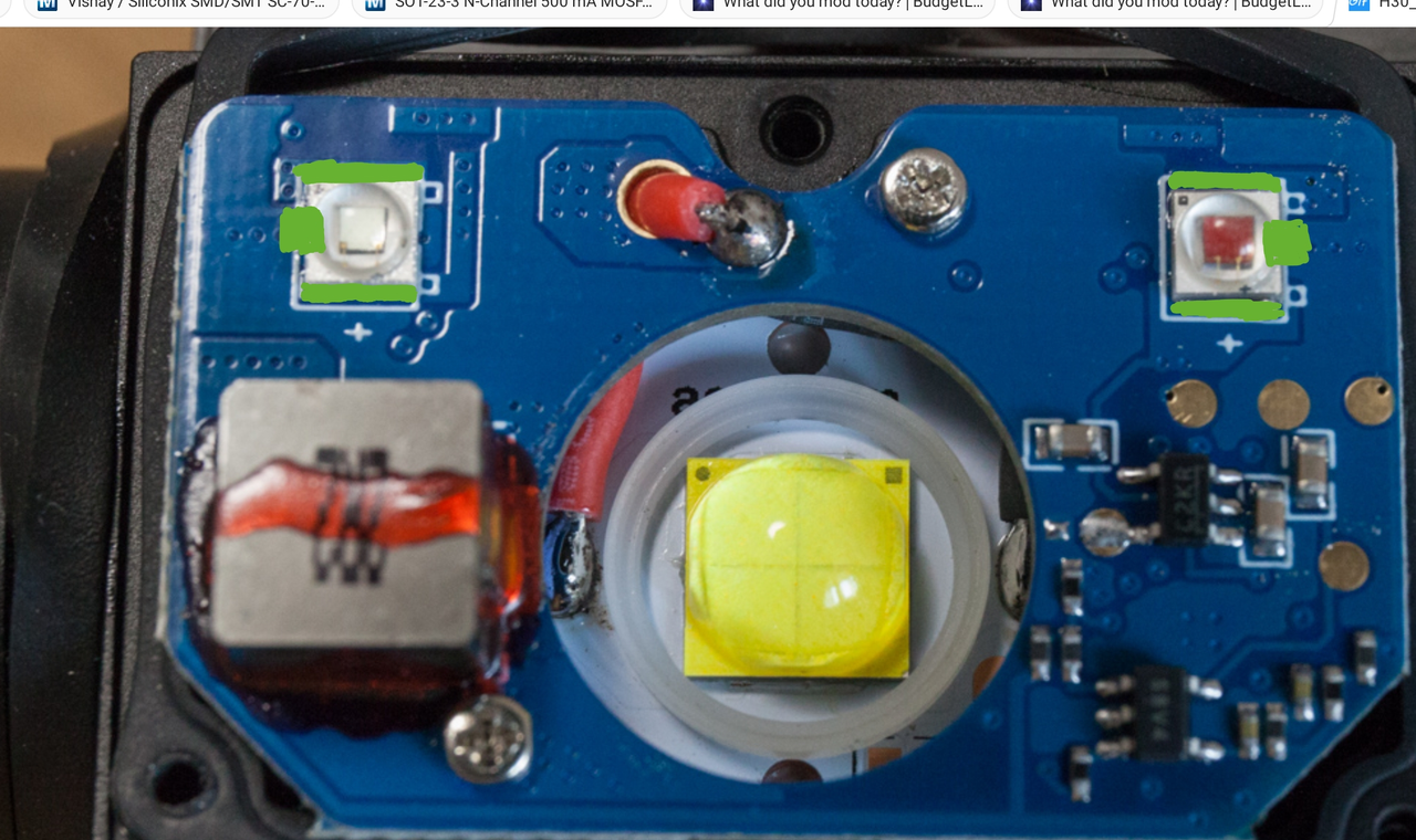
Then I would remove the soldermask (Green markings) so that the exposed copper areas connects to the pads.
Clean the lead free solder, add a generous amount of flux (which you should have in any case) and place the LED.
Apply the iron to exposed copper with a solder blob (preferably SnPb) and wait until it spreads under the LED, repeat for all pads.
I don’t know of an easy technique to remove the solder mask, usually I scratch it with a scalpel or a chisel.