Wow great thinking !
…
Awesome! So these are 12V configuration?
I would guess they’re 6V, but the 6V/12V LEDs are the same I believe, it’s just a difference in which pads the MCPCB uses.
Attempted to fix my Eagletac DX3B mini.
Nice handy little light, but mine had some flaws:
- Gigantic parasitic drain. So much so that I suspect the light was defective. It would actually drain a full 18350 in less than 24 hours while off. This is pretty gamebreaking, because the only way to avoid it is to do a tailcap lockout, which I hate doing.
- Charging port hatch cover is poorly designed. It sticks out, is flimsy, and doesn’t lock into place securely. Not a big issue since the cover is optional. The port itself is waterproof according to Eagletac so the cover is just there to keep lint out.
I noticed that current flowed between the positive and negative pads on the bottom of the driver when the head was not connected to power. I got around 400 ohms resistance, which seemed high.
I managed to remove the driver, but in doing so I ripped off the 3 tiny wires for the charging port. Oops! Even worse, they were so tiny that even after spending 15 minutes with a magnifying glass I could only find one of the bondpads that they were attached to. I ended up permanently disabling the charging port by clipping off its wires.
This light was a royal pain to reassemble. I have no idea how they managed to assemble the thing at the factory. The plastic jacket that sits inside the rubber switch presses so firmly against the switch on the driver board, I was barely able to get it in even after filing the corners down.
Without the charging port attached, resistance between the positive and negative pads on the bottom of the driver jumped to 685,000 ohms. Hopefully, this means less parasitic drain. My cheap mini DMM doesn’t measure current so I’ll stick a cell inside tonight and see what the charge looks like tomorrow.
Guess I’ll also epoxy over the charging port since it’s no longer functional.
I like it but I would like it better if it could have proper MCPCB fixation. I mean is it possible to have absolutely firm MCPCB with some kind of magnet or other type of fixation?
Yes 2 hands are better than one but only if mcpcb is fixated… If mcpcb is wandering around on touch(emitter centering, final tap press) it is still better to do Old Lumens method with small benchvise and big soldering iron tip beneath mcpcb (regulation over soldering Iron station is possible).
But I would like your system better only if there is possibility of MCPCB fixation. Because we don’t actually have 2 free arms if I got to hold MCPCB with one hand and then centering with other (for emitter centering and final tap or press)?
A magnet would not work as copper stars are non magnetic. You would need some kind of clamp or screws.
Yes you are right! I would like Djozz system but with any kind of MCPCB fixation method.
Kapton tape should hold up for a bit
My Kapton tape barely sticks to anything. The glue is very weak. Maybe other Kapton tape is stickier?
Or Liquid Electrical Tape maybe? I threw my Kapton's once i found this marvel
Today I swapped the quad XP-L HI LEDs in my D4 for 4x LH351D 4000k. Probably one of the easiest swaps I’ve done as the new copper MPCB from mtnelectronics was plug and play with the D4. I like the tint much better.
Now I need to find a new home for the quad XP-L HI board.
Forgot to post this earlier. I also swapped a 219C 4000k into an I5T EOS.


Driver is the same??
Not really a mod but maybe useful for someone. As you all know Petzl Swift RL is not really waterproof, it’s only IPX4
Since you can’t really do much about the plastic body as it has too many holes I was trying to waterproof the electronics with 422C Conformal Coating
Here are some photos of internal components:
! !
!
! !
!
The electronic board with two Osram Oslon ? leds and photo sensor on the left side

The other side with heatsink and controller ( STM32F )

Closer look at the LED emitter

The board after coating applied ( in UV )
Modded a Wowtac A6 last night into a triple. New emitters are SST-20 95 CRI.


I used the stock driver. I didn’t even remove the driver to drill a new hole for the driver wires.
I filed off around 1mm of the edge of the star on all sides so it would fit, then I filed 2 notches in the star for the driver wires, and used short bits of wire to extend the stock driver wires to the contacts on the star. I also snipped 1 leg off the Carclo 10507 optic as it was getting in the way of the inside knob of the USB port cover.
Put it back together and it works.
Nice work! Sounds like it was one of those great moments where everything just comes together. Love when that happens.
This looks really useful, but what if the button fails? Can it still be replaced and coating reapplied?
Yes, the coating is flexible it can be removed and reapplied
Additionally it’s Fluoresces under UV-A light so you won’t miss any uncovered parts
It seemed that way at first.
… but then problems developed. Sometimes after battery changes I noticed the light was staying on at a low level even when the switch was off. Then it got worse and was staying on at a higher level. I spent last night trouble-shooting it:
- Perhaps the problem was a short under one of the stars or between one of the jumpers on the Noctigon. I removed the star and reflowed the LEDs and jumpers. But that didn’t fix it.
- Perhaps the unusual arrangement of 2 wires at the sides to a triple was causing issues. Maybe when I screwed down the bezel it torqued the driver wires causing a short through the silicone insulation. I removed the driver, drilled a hole through the center of the shelf and redid the driver wires with a more conventional “through the center” format for a triple. That didn’t fix it either.
- I checked the star outside the light and noticed the LEDs did turn on at a low level when I connected negative to ground and positive to the positive on a battery showing a short somewhere at the star. But reflowing again didn’t fix it.
- Finally, it occurred to me that my filing of the edges of the star might have created a short. BINGO… that was it! When I filed the 2 notches for the driver wires they lifted up the mask slightly at one point. Then when I installed the driver wires it hooked a tiny portion of the contact under the mask down until it hit ground. This was all miniscule and required a magnifying glass to see, but it was enough. I cleaned it up and then it worked fine.
- On reassembly, I also noticed the optic was sitting on ledge just inside the bezel rather than pressing firmly to the star. To fix, I filed down the edges of the optic. (though now that I think about it, a better way would have been to lift up the star slightly by inserting a copper disk between the star and shelf. I also replaced the snipped 2-legged optic with one with all 3 of its legs for more support.
Now it works perfectly. It is nice when the troubleshooting process solves the problem.
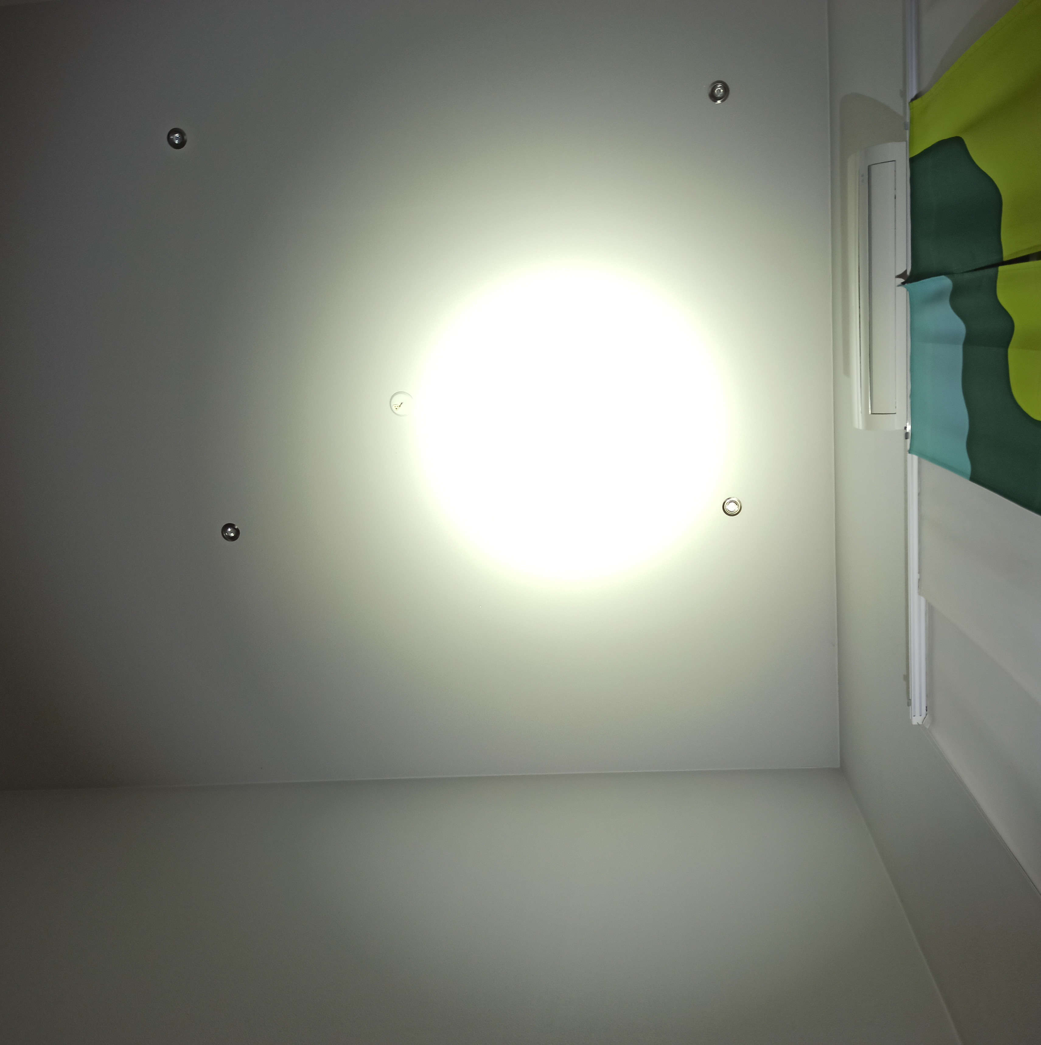
Today I made few visual comparisons between XHP70.3 and XHP70.2. 70.3 is 6000K P2 from digikey and 70.2 is 5000K P4 3A from Convoy flashlight store. I used M21E with OP reflector and camera settings are tweaked so that photos look realistic. Same settings for both leds.
XHP70.3 100%
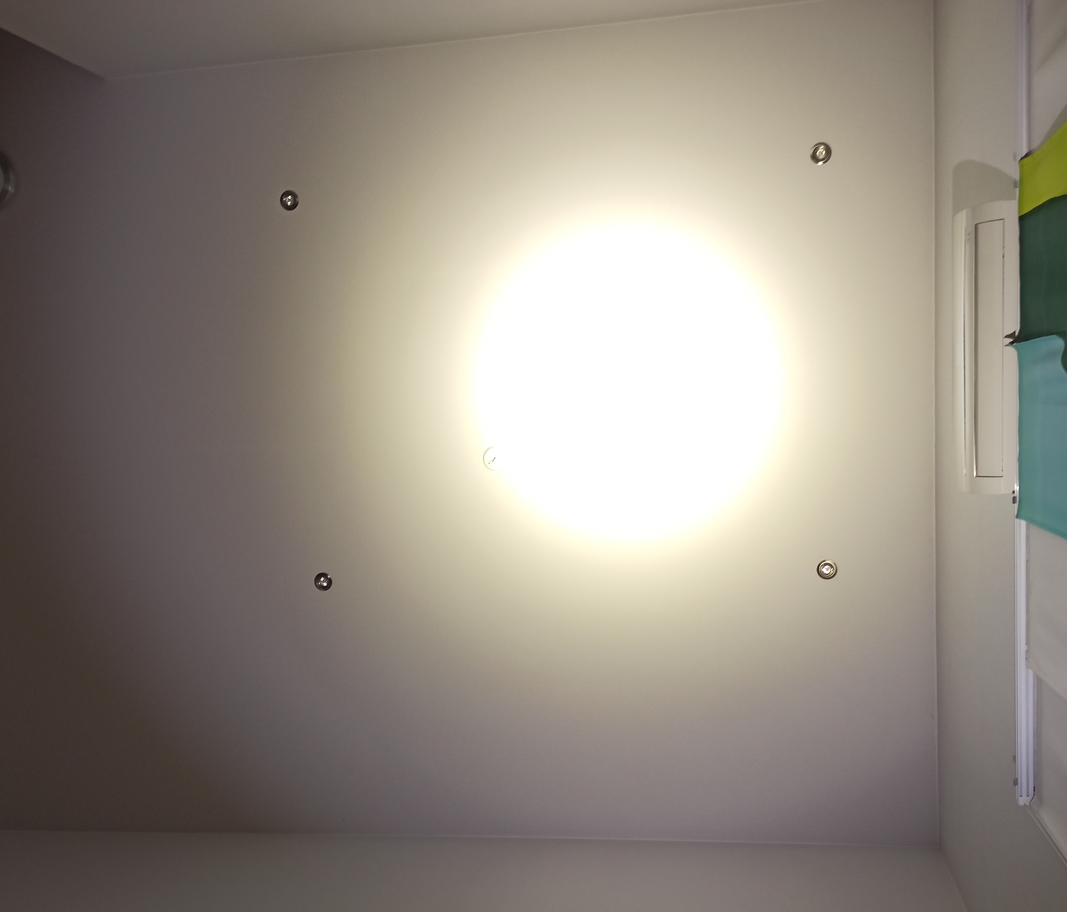
70.2 100%
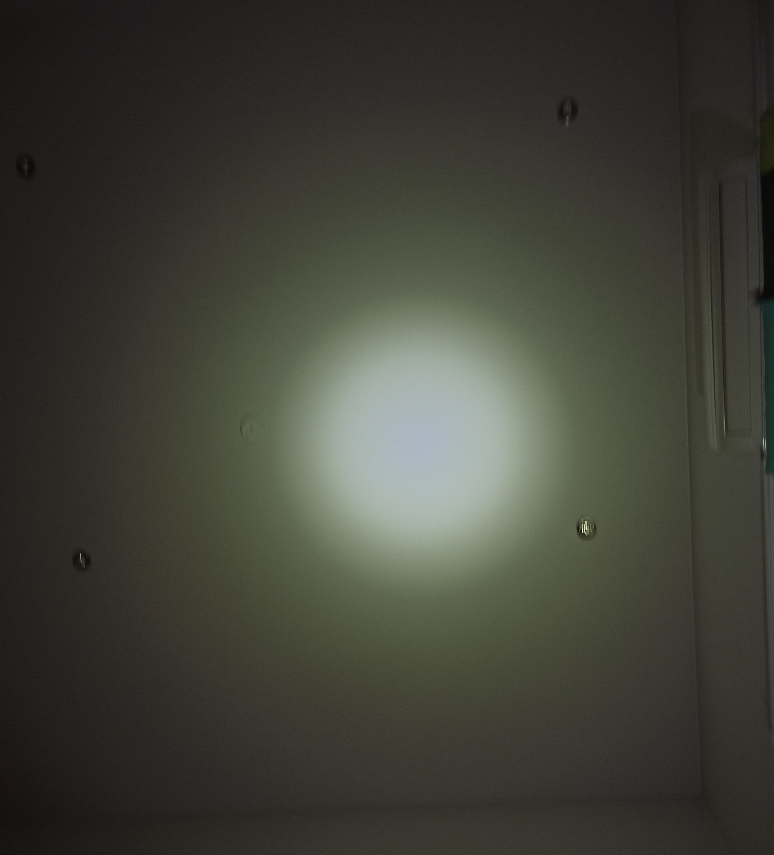
Second lowest step in stepped mode 70.3
70.2 same mode
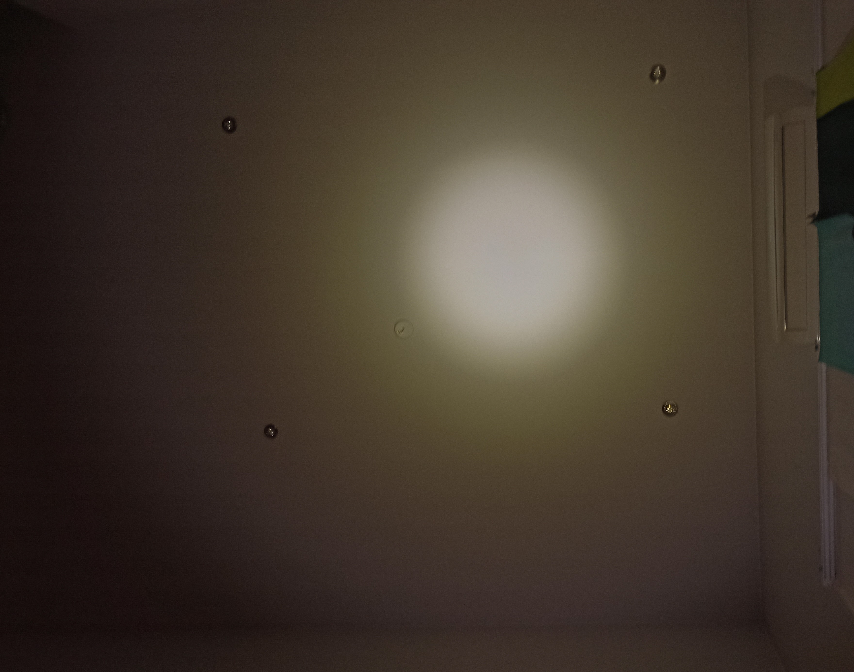
Small difference in beam profiles. 70.3 is little throwier, but it also has big blue center in hotspot. 70.2 has uniform hotspot. Similar tint shift in both leds. Not so bad in this reflector.
I have tinkered quite a lot with Convoys and this M21E’s driver is very different physically than other Convoy ones. It has two horizontal pcb’s that are connected together. Upper seems like normal Convoy boost driver and lower one is probably for the charging circuit and it also has momentary switch directly mounted on it. Two pcb’s seem to be connected together with some kind of rods. Can’t remember excactly. It’s been few days since I opened it.