Love someone else is using a lathe, nothing like my old 1900’s one lol!
I wish I was able to cut threads on mine but sadly it’s almost impossible and it holds me back a lot that I can’t do it, or even know how.
Something I wish to change in the future. Realy looking forward to seeing the finished article!
cool tools. product sounds promising.
Yeah, our school shop has almost every tool I could want to use, short of forging equipment. We have 6 manual lathes and mills, 2 CNC mills, 3- 2/3 axis CNC lathes, and one 7/11 axis CNC lathe (depends if you count the sub-spindle as extra axis), EDMs, waterjet, pneumatic threader, sandblasters, a whole woodworking shop with two CNC routers, two SawStop table saws, welding shop and a lot more. It is like a playground for me, and the best part is that engineering students don't have to pay (outside of tuition/fees).
Unfortunately, I have started to run out of time, with the shop being closed for Thanksgiving and exams looming I might not be able to finish my light. I submitted my files to get made on the CNC lathes but with senior design projects also finishing up, it might not be able to be made before the 8th. If it does get made I will definitely try to take a timelapse of the CNC doing its thing. Even then I still have to get the electronics all figured out.
Well, good luck on finding time. This is my weakness, for life! :).
I don’t know how long is left for the contest, but I’m about out of free time to spend working on it anyway. I am supposed to make pocket organizers for the kids (to hold victorinox knife, lumintop edc01, and rite in the rain plastic variant of Fischer bullet space pen) out of an old suede coat… If I can. Have to try.
I may be crazy but I think that if you know what you’re doing, you probably shouldn’t be doing it, :P. What’s to be learned?
That would be awesome to see, fingers crossed ![]()
Countdown timer… is in the first post here.
For me, if I know what I am doing and am doing it again, it is because I derive enjoyment from it.
While it seems like I might know what I am doing I promise I don’t. This project was a combination with a school class for product design so most of the work went into the design so I hit all of the deliverables for the class, making the flashlight was just a happy byproduct of the class.
In terms of machining, I work at my school’s machine shop but I still have lots of things to learn about machining. For example, this was my first time doing single point threading and while the part turned out nicely, it also turned out as left-handed threads instead of right-handed threads. I also picked up tips along the way such as using the indicator on the tailstock for more precise drilling depth, little things like this that I can pass on to other students when they have similar parts.
The machining process is simple in theory, measure, turn, drill, measure again, realize you are .100” undersized because you read the caliper wrong, curse, repeat. I don’t care to admit how many mistakes I have made working on just those two parts but I also enjoy the process of taking an idea from my mind and then physically holding it in my hand and that makes up for all of the effort it took to get there.
Howdy, just an update and a few questions today. Unfortunately, I won't be able to finish the flashlight, since I don't have to finish the project for the class my job got pushed to the bottom of the list, maybe next semester I can finish it properly. But I'm not done yet, since I have all the electrical components I am working on hacking together a lantern, which was one of my other entry ideas. Once I get more photos and things done I will post an update, most likely Sunday or Monday. My question relates to the electronics and wiring of the driver/eswitch/MCPCB. I remember the driver (MTN-17DDm) came with a diagram but I lost it long ago.
First the battery should be connected to the driver in this orientation with the positive side on the driver and the negative is connected to the ring on the outside of the driver?

Second is the wiring between the MCPCB and Driver correct, does it matter which positive parallel pad I connect to? Also, the most confusing part is where do I put the E-switch in the circuit, I know one leg goes to one of the controller pins. The other lead goes to the negative lead if I recall correctly.

Close up image of the driver

Any help or resources would be greatly appreciated.
All correct, for the switch one wire goes to the OTC (not populated) pad connected to the MCU and the other one to GND, for example on the GND pad of the OTC, or on the 3 legs of the FET next to the vias.
re the e-switch This page indicates pin 2 and ground. (scroll down about 3/4 the way
I have not used that mcpcb but that does appear correct for parallel leds I looked at the sales page, here
Thanks for the quick responses, so if I understand the driver correctly the outside ring is a ground connection, so I should be able to solder to point 1 on the picture? Or do I need to solder to one of the other points I labeled? And if it is one of the pins on the 7135, does it matter which one it is?

Also, would 20 gauge wire be fine for all the power delivery circuitry? I saw that 22 gauge is offered to be added on at MTN Electronics, I just wanted to make sure I don't burn any wires.
Yes the ring is GND, and the one marked 2 as well, the legs of the FET connected to GND are these ones :
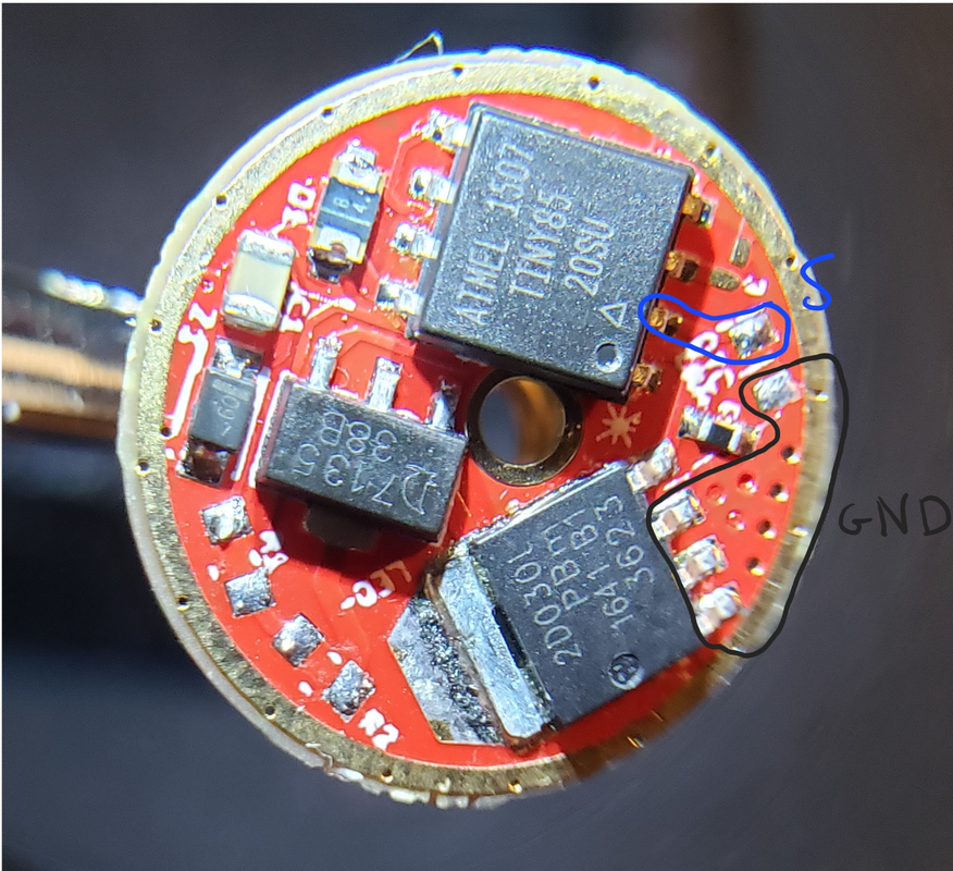
I mentionned it because they’re big and easy to solder on, but the ring works too if it’s not sitting on a shelf like it would in the flashlight.
That’s perfect ![]() Exactly what I meant. If you know what you’re doing, you’re just doing. To learn, you have to not know.
Exactly what I meant. If you know what you’re doing, you’re just doing. To learn, you have to not know.
I’m just getting bad at the SEEMS like I know what I’m doing part as I get older. I just say “I’m practicing for when I get Alzheimer’s. I need to be comfortable being confused and lost and letting these nice kids help me find my way back to wherever the food is.”
Unfortunately, it looks like I will not be able to complete my project, I ended up burning up the contact pad for the switch and then spent 4 hours trying to solder a wire to the #2 pin on the driver with no success. Almost everything else is finished but I won’t be able to get a replacement part in by the end of the competition, guess there is always next year to go big.
Thank you to everyone who gave advice on my light.
You could scratch away the red solder mask and solder to the copper trace. Your soldering iron shouldn’t have too high temperature, you need to tin the pad and the cable and then you can quickly join them.
Yeah, there’s almost 2 hours left - you can do this! Like Skylight said, don’t use too much heat - that can cause pads to lift up. Just use plenty of flux and some good solder. You’ve come so far, I’d really love to see you pull it off.
I wish I could have, but unfortunately, Wednesday is the last day of the school year and I am currently taking a break from writing an essay on Computer-Aided Manufacturing. I definitely learned that I need to start much earlier. Are there any rules on making unofficial entries for the next year’s competition before the official thread starts? I think I might start working on designing a new light sometime this spring work on it when I have more free time.
I don’t think you can really start before the competition, but I think doing a practice run or two and posting about them would be a great idea!
Usually when I’ve seen solder pads lift, it needed less heat and more flux.
However, somewhat counterintuitive is that a hotter iron can sometimes deliver less heat: you are able to create a steeper temperature gradient, and more quickly solder the joint with a hot iron. An iron that is too cold will have to slowly heat not just the joint but a bunch of the surrounding area as well. Sitting on a pad with a 250°C iron for 30 seconds is way more likely to lift it than a 2 second poke with a 350°C iron.
This is where soldering gets tricky and balance has to be found. When I soldered to my SBT90.2 MCPCB which was soldered to a chunk of copper, I used the highest temperature and largest tip my iron had so I could rapidly melt the solder on the pads without the half-pound of copper absorbing all my heat faster than I could use it.
I know that the contest is over but I thought I would keep updating the thread until I finish just to keep others in the loop.Now that I have finished all of my classes I have the rest of this week to finish my light before going home for winter break. To make the light I am using a HASS TL-2 Lathe and programing with MasterCam and using the lathe's built-in MDI programs for some of the more basic operations. Unfortunately, I am still not the most proficient with the controller and managed to screw up some offsets and will be remaking this part tomorrow.


Here is a video of the machining process. I removed the audio since I was working near some other people and didn't want to invade their privacy. I also apologize for the shakey camerawork, I will try to rig the phone up to something more stable in the future
