Just received a TS21 in RED w/sst20 4000K. It's awesome!
Has one strange issue - the BLUE switch LED comes on and off intermittently, on it's own, usually during usage. Funny I've seen the same exact behavior with the Astrolux EC06. Seems to be reproducible with the light cold, sitting for a while. Didn't check if the TS21 is using the same USB-C charging controller chip as the EC06 but I suspect it is. I believe Sofirn makes both the Astrolux EC06 and these Wurkkos lights. The BLUE LED is from the charging circuit. I get the same BLUE LED on if I connect for charging, then disconnect the BLUE LED stays on solid for a while -- strange behavior.
Wurkkos - can you guys verify this behavior? Anyone else see this?
Mine has the same behavior. The blue light will randomly come on after power off for maybe 30 seconds. I have the gun metal grey version 2. It’s an awesome light, my favorite actually. I’m wondering why it does this too?
It's designed this way, same as the EC06, same as the SC31 Pro - way too low resistor values used like 1K or 0.5K, when 6K-12K should be used. With the TS12, the amber at this intense level looks way too bright, but the low is very hard to notice - probably has to do with the mech design - poor placement, poor optics for the switch LED. I see other lights using a switch cover that's not very translucent - details, details...
Ooops, yep. SC31 Pro. Recently got 5 green ones to gift, but did minor checks/updates. All 5 had a 0402 1K resistor for the switch LED's, and even my older black SC31 Pro had the same 1K resistor. Swapped them out for 6.8K - much better, low and hi still good visibility.
Hi went from about 1400 uA down to 271 uA. So Yes, stock SC31 Pro has high parasitic drain for switch LED on Hi, way too high.
With 6.8K resistor: OFF: 34 uA, LO: 75 uA, HI: 271 uA
Probably could even use a bigger resistor like a 10-12K and still get good LO/HI output.
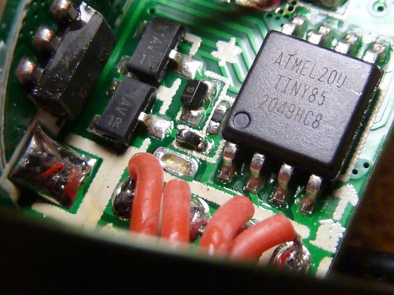
There she is, had a pic, to the left of pin #1. Easy to remove with a wet iron tip, I used very light amt of solder paste on the 2 pads then used the iron on one end to simply get it in place, then hot air - worked well.
I’ll probably leave it stock and just use low level. My soldering skills suck lately. I checked my SC31 Pro. 1.4 ma on high, 90 microA on low and 41micro A on off. I can see the low pretty well so not so bad.
Does the built-in Anduril and/or Anduril-2 "Low Voltage Protection" which activates at ~2.8 VDC eliminate all parasitic drain on the battery, so that the battery cannot be discharged any further whether the processor was "in-active-use" or while it is "idle-and-sleeping"?
I have no experience with the micro processors used for Anduril, but I understand how they would be able to stop power from being supplied to the main or aux LEDs (including the switch LEDs).
What I am wondering is, does the processor still need to have a parasitic drain on the battery in order to determine if or when the battery's voltage is above the low voltage cutout or is there some other type of circuitry that totally eliminates all current when the battery voltage is below the low voltage cutoff and if there is a parasitic drain after the low voltage cutoff, how large is it?
I think it does turn off the switch LED's in LVP - it wakes up periodically when the MCU is asleep. I believe in the wakeup period, it draws about 3-4 mA, but again it's only for a short duration at a periodic scheduled time slice. I don't know all the specifics though, but of course it can't do anything about the charging circuits - those are independent.
I think at the final moment of reaching the bottom level, it shuts everything down.
Of the TS21? Hhmm, probably not a full tear down but if I open it up to fix the high drain, I'll probably take and post pics. I'm not sure I can get low mode to be viewable though because of the design - type of switch, position of LED, etc. Funny, I've found the low mode hold it's own when upping the resistor value, but the amp draw in Hi mode really drops.
Well, I did pull the glued driver and do see low is super low, barely lit looking straight at it. Also noticed there's 2 double LED's and one was just about fully covered with that red liquid electrical tape stuff, so pulled it all off the LED. tracked the resistor from pin #3 of the MCU - it's a 0402 100 ohm :FACEPALM: , figures. Should probably be 6 - 10K or so. The pin #3 output does go through aa 3 legged part as if the LED is being shared - not sure if it is or not, maybe the USB-C controlle,r and maybe it puts out lower voltage or something, dunno.
The LED wires are tight, so to remove the driver, first thing you need to do is un-solder the LED wires, then I used a solder pick through the center hole and gave it a few taps, being sure to keep the pick over to one side at the edge - important so no IC's are damaged. Came out easy them. The driver glue is a wet glue, weird, usually it's dried hard but this was still soft/sticky.