BTW the drain in your light is much higher than mine, which is 3 mA on High, 80 µA on low, and 30 µA while off. Maybe the Anduril 2 version has something to do with it?
Also I found that removing the sheet under the optic doesn’t seem to affect the beam really, but it does allow the switch light to shine through the front which looks pretty cool.
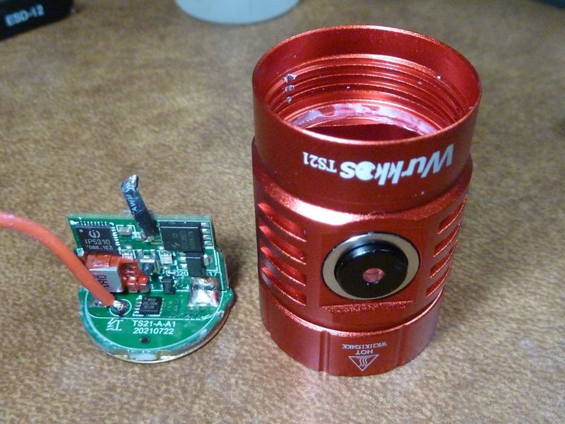
They changed the USB-C controller I assume, because the new rev has new features - power bank, more power, etc.
Again, I am very suspicious of the USB-C controllers these guys use, and total lack of testing of the parasitic drain these things cause. Could be the designed usage of the part or the part itself, dunno.
3 mA is still bad though, very bad. Should be no more than 300 uA total with the switch LED on high.
Huh well you make a very interesting point there! The powerbank functionality seems a great function to me for a light that I always carry in my backpack, but if it’s empty before I can use it (even though I regularly check it) well what’s the use in that!
Side note, I suppose it would be quite easy (with the right hardware: hot air gun) to swap the two combi-LED’s right? I would prefer to have the orange LED on the button instead of the green one… I have a black TS21 on it’s way and the hardware is slightly different there I think in the case of the LED colors compared to the colored flashlights (those seem to have the LED colors already differently)
Hhmm, I guess should be fairly easy - I don't have any double LED's, got lots of singles in different colors. Wondering if the poor low output or high drain is the LED or the color amber, some how related to the drain.
Neither do I, but I’m thinking to just swap the LED’s they used on the board, but I’m not entirely sure if the different voltages of the red/green/orange/blue LED are interchangeable with maybe different on-board current-limiting resistors…
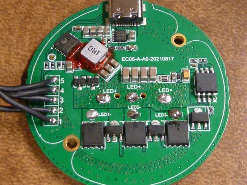
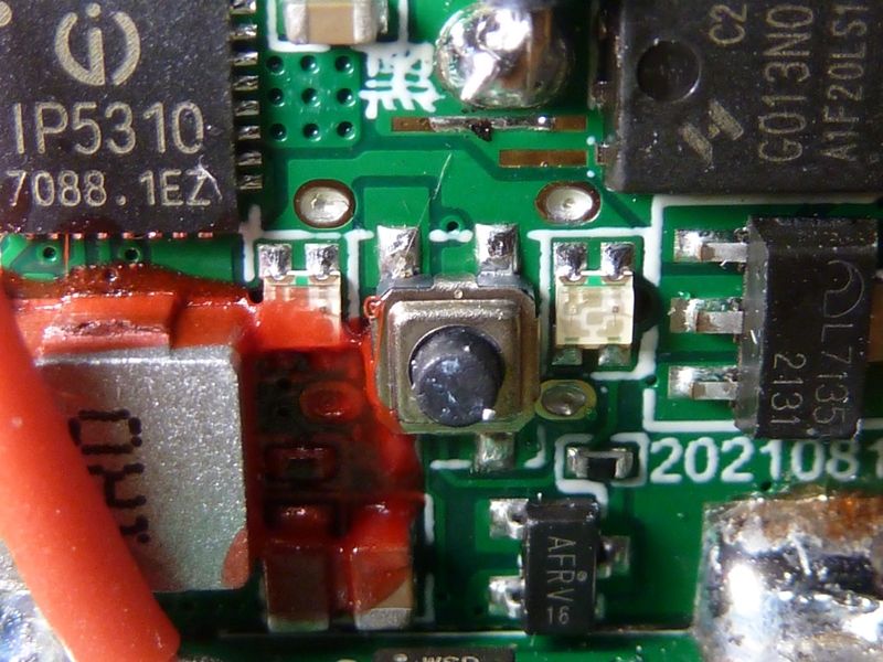
Well the stock current limiting resistors are both 100 ohms, very low, should work with just about any color. You can see them here in this pic, the 0402's just below the LED's, below the switch, horizontal. The left one is covered over with red junk:
Hmm, I’ll try to give it a shot to measure that, I suppose I can power it with a bench-power supply at about 4.2v and have a low current measuring meter in between measuring leads that I press against the pads, since I can’t simply remove the back of the battery holder :innocent:
Ah yes I see them thanks! Yeah that gunk might cause a bit of trouble if I end up trying to swap the LED’s… I also wonder if it has an effect on the color the LED produces?
To measure drain, I just remove the battery tube, sit an 18650 batt+ on the batt+ brass ring, and use a DMM meter across the batt- to the ground ring: easy.
I carefully removed the red junk off the LED - dunno about it's effect because I swapped resistors in the process - 100 ohm to 8.2K, but only for the amber color.
Ah, yes good point, that’s also another way of doing it!
… and also for the blue LED then right? Because they are both in the same package and use the same current limiting resistor? Or are there two more resistors somewhere else on the board?
I believe 1 resistor is used for amber (1 side of each double LED), 1 resistor for Blue. I don't see separate resistors per LED, and each double LED acts as 2 distinct LED's, separate wiring, 4 connections.
Yeah turns out I won’t be needing to swap the LED’s, the main light is already orange instead of green. However, on low you can’t see anything of the LED, that’s a shame… And high is too bright I guess, maybe I’ll change those resistors instead…
Also, I have to say it charges quite fast, a bit too fast for my liking. It peaked at 5V 2.9A and the battery for sure got hotter, the Q8 Pro charged at “only” 2.6A max from what I’ve seen…
EDIT: luckily it didn’t overcharge the battery as well, I measured 4.17-4.19V
I measured the “parasitic” currents of my black TS21 with Anduril 2 with a Current Ranger from LowPowerLab (no auto-lock or hybrid memory mode, locked or unlocked is about the same):
LED low: ~150 µA with regular jumps to to 300-400+ µA
LED high: 13.7 mA (what?)
LED off: ~95 µA with regular jumps to to 300-400+ µA
I also measured it for my Q8 Pro (no auto-lock or (running) hybrid memory mode, locked or unlocked is about the same):
LED low: ~135 µA with regular jumps to to 300-400+ µA
LED high: 3.2 mA
LED off: ~90 µA with regular jumps to to 300-400+ µA
So yeah, my TS21 measurements are about the same as yours, and unexpectedly the currents of the Q8 Pro are lower. With the LED on high even way lower, even though the Q8 Pro (I think) features 2 LED’s. I suppose it’s down to the different LED color, and maybe current limiting resistors?
EDIT:
I also measured the same currents for my IF25A:
LED low: ~80 µA with regular jumps to to 200-300 µA
LED high: 1.5 mA
LED off: ~40 µA with regular (but less frequent) jumps to to 300 µA
I pm'ed Barry from Sofirn about these high parasitic drain issues - we'll see.
Just received a Mateminco MT70 Mini (FT03) w/SFN55.2 running Anduril, measured:
LED low: 48 µA
LED high: 101 µA
LED off: 20 µA
This is where the #'s should be for most lights! 20-40 uA on OFF is acceptable, any higher, something is wrong - there's a leak!
Lumintop EDC18 - Anduril, switch LED always ON, not controlled by Anduril:
85 µA (no option on switch LED)
FT03 Mini w/SST-40, w/switch LED's and 4 LED's around the main LED in multiple colors, Anduril:
LED low: 120 µA
LED high: 3155 µA
LED off: 22 µA
For this MT03 Mini, the OFF and LOW readings are fine, but the high is way too excessive - no need to be this bright, but this is a definite "bling" light with all those extra LED's around the main LED. It probably would be fine at 500-1000 µA by adjusting the resistor.
I'll go along with a HIGH reading of up to 300 µA - that's acceptable. Any higher means the resistor value they are using is too high, or something is restricting the switch LED output, so they had to up the output to make it bright enough.
The "regular jumps" noted above is the standby checks for LVP, maybe other housekeeping - that shouldn't be a factor because of it being infrequent short durations (though it's longer and more frequent than I would like).