Thanks NeutralFan ![]() It is better than the original beam. Even better only if it was High CRI.
It is better than the original beam. Even better only if it was High CRI.
As for the underlined words, it is just for emphasis , not links ![]()
Thanks NeutralFan ![]() It is better than the original beam. Even better only if it was High CRI.
It is better than the original beam. Even better only if it was High CRI.
As for the underlined words, it is just for emphasis , not links ![]()
With that and the TIR, I understand your satisfaction!
You bet I am more statisfied with the new configuration ![]()
It is more pleasant to use this version now. I have to test it outside in normal use but I believe it will become one of my favourite lights ever :innocent:
Ok, I did it again.
My little family of multi color flashlights got an addition:
It’s the tiny S2+ in the middle. It got a white LED and two color LEDs, red and blue.
I designed and built color drivers in the past but unfortunately they were to big for the S2+. So I decided to use one of the old Blf X6 drivers I’ve still laying around. Again I used D882 transistors to drive the color LEDs, the base resistors limit the LED current to about 1 A. Base and pull down resistors are directly soldered to the transistors, then I encased them in flexible thermo glue, for electric insulation and some heat transfer to the pill.

I modified the Blf X6 driver for OTSM with a big capacitor and removed OTC and voltage divider resistors, since I do internal voltage measurement in my firmwares. With a quick test rig I checked the function.

In the next step I glued the transistors into the pill and completed the driver.

Btw., I used a triple color MCPCB from Kaidomain which I ordered a while ago and replaced only the green LED for a warm white XP-G2. This boards are still available and come for little money with optics included. It’s not a Carclo but still pretty nice.
I extended my latest clicky firmware for 4 channels (7135 + FET + 2x color), it does smooth ramping and has some other features. My favourite is the 2 color emergency strobe.
Here are some more pictures and a short video which demonstrates ramping and the color strobe.


Very well done, makes me wish I could build drivers and program firmware!
What magic you do!! ![]()
![]()
I had to switch to my PC to see the full impact of the detail work. ![]()
That’s a lot of wires to cram into the pill! Nice job Flashy Mike.

Another mod with the Nichia 519A SW45 R9080 from Simon, sliced in a Sofirn C8F. I modded this C8F before with a Lumintop GT-mini driver (Narsil M user interface) and 4000K Luxeon V leds, I kept the driver but changed the leds for the sliced 519A’s, for less output but better CRI, a super tint, and a bit tighter hotspot.
At low output:_ At highest output (2500lumen):
CCT=3620K__CCT=3970
Duv=–0.0019__Duv=–0.0058
CRI=96.7_CRI=94.3
R9=92__R9=87


Did I mention Foy-bezel? ![]()
The metered readings make it appear to have a pleasing light output
Only greasing & N219B sw45k D220, I even had a MCPCB with LED left. But I like this light. And now I like its light.


left to right: M11R N219B, 2019 RRT01 XML2 5D, 2012 RRT01 XML2 3000K (CRI 80 or so), V11R XML2 3C
Nice! The Foybezel does it :+1:
Xpl Hi 2850 80 CRI


Another addition to my family of multi color lights:
Again a Convoy S2+ but a bit different from my last multi color build. It has the same BLF-X6 driver, modified for 4 channels and OTSM, with my ramping color firmware. But this time I wanted some more cell capacity so I decided to build a 18500 shorty. I couldn’t shorten the pill as much as other modders did, since I need the full space of the pill for the additional D882 transistors which drive the color LEDs. Also I didn’t want to glue or solder the driver into the pill (which would save some space) since I have to open it from time to time in order to update my firmware.
So I sanded as much as possible from the front of the pill but let the shelf there. Its thickness got reduced though, it is about 0.3 mm now. I also sanded the back of the pill including retaining ring to gain some more space. Instead of the driver spring I used a sanded brass button. Another bit of length I won by sanding the retaining ring of the switch PCB.
Despite this efforts the 18500 cell (although only 49 mm long) is still too long for this shorty. So I 3d-printed a spacer which I put between head and battery tube, with a height of about 2.8 mm. Now everything fits nicely and the cell flushes with the end of the tube. I’m thinking of replacing the printed spacer with a copper one, a piece of a common 24 mm copper tube with a wall thickness of 1 mm should fit perfectly.
The used LEDs are a very nice 92CRI Nichia 219C which Kaidomain sold a while ago, and a red and a green Cree XP-E color LED. Although I intentionally used thin wires the current draw of the Nichia is still pretty high with about 7 amps. The high capacity 18500 cells I use for this light are rated for about 4.5 amps continuous current (6.75 amps peak) so I configured my driver to limit the output.
These are the D882 transistors which drive the color LEDs with pull down and base resistors, insulated and glued into the pill with flexible thermo glue:
Sanded pill and 3d printed spacer on the tube:
Done …
I swapped a 519A in a SS Enogear and found it way too floody.
After gently pulling, the whole and complete dome came off, not leaving any residue on the glass of the LED where the dome sits on.
The tint is perfect and the hotspot is smaller, but way more usable.
It clearly shows signs of the dedomed LED, where the hotspot is not round and not square, but i like it!
Any pics Yokiamy? Curious to see how your 519A looks after dedoming.
I modified my LH351D 3500K T2 by installing an AR lens and a lighted switch. Of course I took everything apart and “fixed” some things along the way.
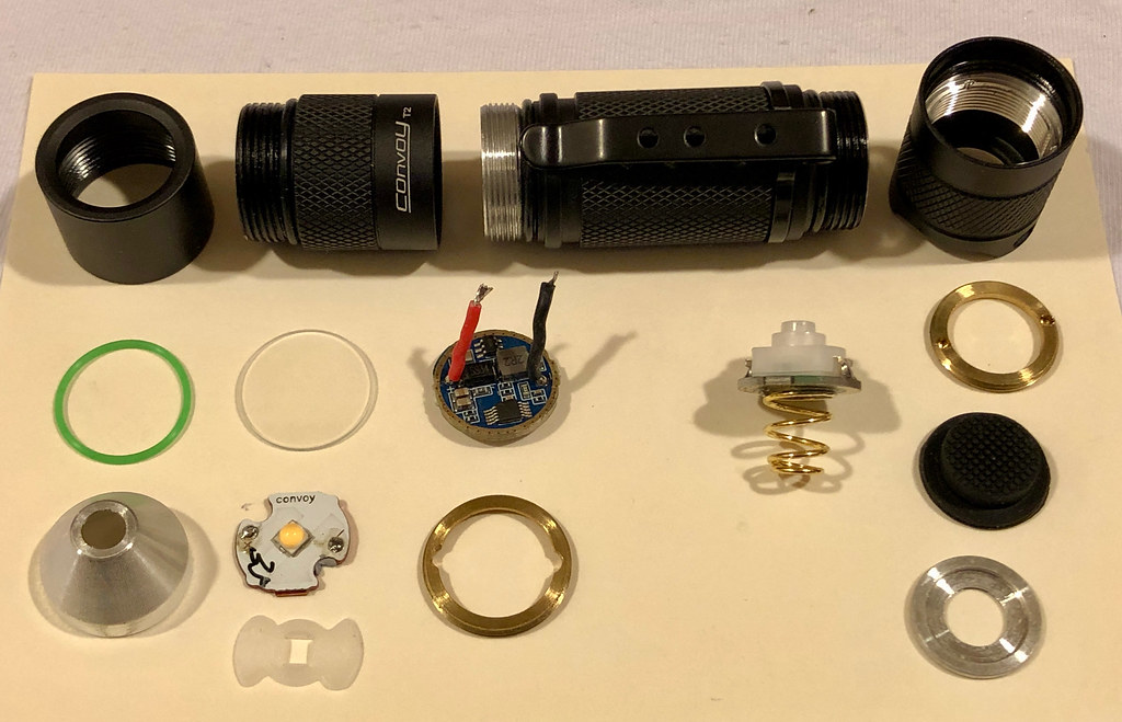
When I went to solder the LED, I noticed that the MCPCB didn’t sit well on the shelf. The snap-off spot was hitting the side of the shelf. So I filed it down and then it fit no problem. I like how the 1mm x 15mm MCPCB has little protrusions that fit into the other 2 holes of the shelf so it doesn’t rotate when the reflector is installed.


I noticed that there was a gap between the driver and the retaining ring. The driver was too wide to fit inside the groove of the retaining ring. So I sanded down the perimeter of the driver to make it fit.


BUT, when I went to install the driver there was not enough threads left in the head to tighten it. I guess that’s why it was left that way!
So then I made a spacer from a spare retaining ring to fit inside the T2 ring and that resolved the issue. And I think it looks better without the gap.


The lighted switch was a little bit of a challenge since the new Kaidomain clear silicone tailcap was slightly different than the original black one. When I first installed it, it was hard to turn on the flashlight since the button was too far away. So I sliced the tips of 3 switches and superglued them onto the new switch. Now it works perfectly.


The mixture of purple and green 0805 LEDs makes a nice light green color and draws 0.09mA.


I like the tint and beam of the “U6” binned LH351D LED which appears accurately to be under the BBL.


Nice mods NeutralFan, I like to finetune my everyday use lights too, but even nicer pictures, those will help other modders a lot!
Not the best picture, but from left to right, 519A dedomed, 2700K SST20, original Neutral White (XPG2 ?)

Looks good Yokiamy. I was actually curious to see how the 519A LED itself looked after you dedomed it.


 .
.