Thanks
I haven’t tested the SC64c LE (3V), only the SC64 (12V), the former will likely be more efficient, I’m not sure what is exactly the issue with the TPS61088 used in the SC64 but the efficiency drops at 12V output, boosting to higher voltage (12V vs 6V) is a bit less efficient but not that much.
The H04 is in my opinion not very good, it only goes above 90% in dropout (i.e not stepping down the voltage), they’re cheaping out on components : high resistance path (about 220mΩ) and asynchronous topology.
The SC600 III/IV and SC700 have pogo pins, I don’t know which part exactly they use but similar pogo pins from Mill-Max have a max resistance of 20mΩ, and with the amount of them the total resistance should be quite low (6 in the SC600IV for example = 3.3mΩ max)
The SC64 does have a thin steel spring like the H600 but there is one less spire and maybe they touch themselves when compressed, in the the H600 spring doesn’t compress a lot with unprotected cells, in practice the tailcap can get quite hot in turbo with the H600, showing that a significant amount of power is wasted, but it does not seem to be the case with the SC64 (but it also draw a bit less current so…).
Personally I bypassed the spring on my H600s, virtually eliminating the resistance.
I haven’t disassembled my SC64 LE yet but I will measure it in the future, it’s a 3A synchronous buck driver based on the TLV62085, it should be more efficient.
Regarding drivers having better efficiency it’s mostly about using better components : lower resistance PFET (for the reverse polarity protection), inductor, sense resistor, switching/rectifier FETs, for converters IC they’re integrated in the IC, so it’s about choosing a good converter, and one with synchronous rectification i.e the rectifier is a FET and not a diode (asynchronous).
I hadn’t considered the relative efficiency here; yeah, the SC700 XHP50 rather trounces the H04. That’s sad to hear they’ve cheapened out on components for the H04. I wonder how the M200 series fares in comparison…
I upgraded my measurements setup, before I used 2 Uni-t UT210E current clamps (2+3) , an Uni-t UT139C (0.5+2) and a RDtech ”precision” voltmeter.
Now I measure the current across 0.1% current shunts with a BM867s (0.032), Aneng AN870, Owon B41t and a RDtech precision voltmeter, the 3 later voltemeters are calibrated against the BM867s and are within 0.02.
Are losses in efficiency somewhat linear with output current when using Monolith boost converter? If Emisar/Noctigon driver has 95% at 2A, this has 92% at 2.5A then how probable is it, that this driver would have ~88% at 3A?
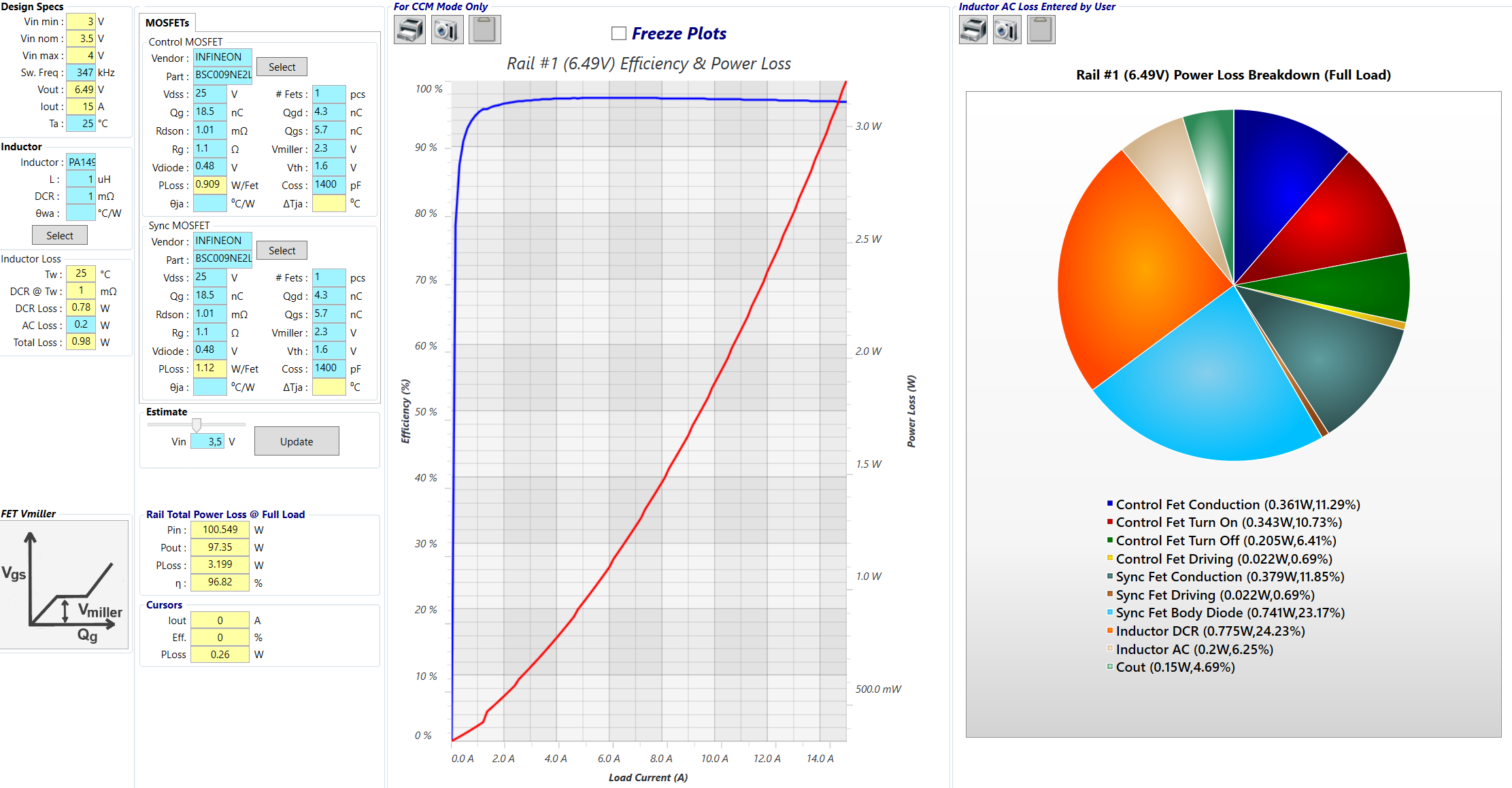
Well power losses are not linear (which would mean constant efficiency), a large proportion are conduction losses (I^2 x R), but you can see from my graphs (I should redo them with my new setup) that efficiency points aren’t linear either, but especially I think it’s the temperature increase that greatly increases power losses at high currents and tanks the efficiency, because running simulations without temperature modelisation gives a fairly straight efficiency curve.
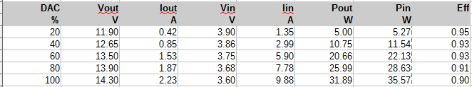
Anyhow the Emisar boost driver efficiency is lower than that according to Hank’s measurements :
Which isn’t surprising since the inductor is smaller.
Edit : Vout is also higher.
Uses the MP3429, 600MHz synchronous boost converter with integrated switches, ~12V output.
6030 0.68uH inductor
AON7423 RPP PFET, <5mΩ at –4.5V, <6.5mΩ At 2.5V
Rsense = 150mΩ, Vsense = 150mV
The efficiency isn’t as good as it usually is with this converter, it has quite thin traces, fairly high current sense resistor and too low inductance.
Input capacitance is quite low (one 0805 capacitor), I had to add a bulk capacitor for making the measurements as it didn’t work properly in turbo.
For high power converters (integrated FETs) I don’t think so, Analog devices’ highest switch limit boost converter is 7A (and it’s a dual phase, 6A for a single phase one), whereas TI has two 10A ones (TPS61088, TPS61178) and a 15A one (TPS61288) and MPS has several above 10A. But for lower power there are many manufacturers
What do you think would happen if using 2 boost converters in parallel or series? Is it viable to achieve higher output currents without hit to efficiency when using parallel setup for example?
For parallel I think you need some sort of load sharing mechanism otherwise one converter will deliver most of the current, for series I’m pretty sure the output needs to be isolated.
Using those converters the simplest thing is IMO to create a dual output driver and have 2 separate LED channels, which is possible with multiple LEDs but also with XHP50/70 since they feature 2 separate strings of 2 series LEDs, the MCPCB needs to be modified though.
Another way is to use a boost regulator (external FETs) like LTC3786 with low RdsON FETs for higher power, several regulators can be put together to run several phases for a very high power single output boost converter. But with this even just one phase takes more space. Loneoceans GaN driver for example uses a boost regulator and well, GaN FETs, probably uses that regulator actually.
Why would one converter deliver most current? In mechanics you could use two pumps to suck from one pool and both pumps do the same job and deliver the same amount. Is there some different principle in electronics that I don’t get? Sorry for off topic in your thread.
I don’t think I have sufficient space with the inductor I chose (1580 sized, 0.42mΩ), if I were to add USB-C charging I would probably need to use a 1010 inductor instead (like XAL1010 1uH 1mΩ).
I guess this is due to the output regulation.
With two pumps immersed at the same level and at the same power they both produce a similar pressure and the small difference there might be between the two doesn’t disbalance the current of each much. This is a open loop control.
With a DC-DC converter we want a constant output voltage (for example), if Vin and Iout is always the same then you could use a fixed duty cycle D = 1-(Vin/Vout), as with the pumps it’s an open loop control. But since Vin and Iout (causes voltage drop) will change then you won’t get a fixed Vout, so instead Vout is compared with a reference Voltage (Vfeedback), if *Vout<Vfb then D increases and vice versa, it’s a closed loop control.
The problem is that Vfb isn’t going to be identical between two converters, so one might regulate to 6V and the other one to 6.05V or something. So the 2nd one targets 6.05 V by increasing the duty cycle, the second one will keep decreasing its duty cycle because it wants 6V and 6.05V is always going to be too much and will end up doing nothing.
With the constant current regulation I think it will be the same.
That’s my understanding of it.
Might be. But if also feedback is parallel, then it should be same to both? Doesn’t it depend from led VF from which it’s stepped down with resistor. If both converters read feedback from that same source shouldn’t both boost converters still think they have same job to do? Might be worth trying if I ever find motivation to start planning my own driver.