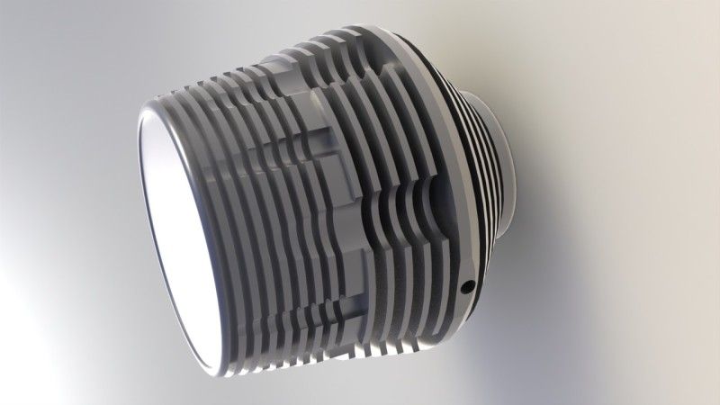
Here is a housing I have drawn up in Solidworks. It weighs 90g and can easily dissipate the 30W of heat when riding at 12mph.
Rendering takes ages so there is actually one more shallow fin which you can see in the following pics. Simple little adjustments meant the stabilised temperature fell from a hot 114C to 65C. A chamfer here, extra depth groove there makes all the difference. I found the 'firewall' as I call it, the depth of solid metal behind the LEDs, to be at the mose efficient at no more that 4.5mm. Any more and the weight went up with no noticeable improvement in cooling.
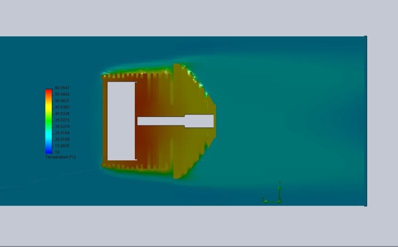
The test was done with an initial solid temp of 60C to speed up the calculations. Air speed at 12mph, my normal riding speed when needing 3000 lumens! Air temp at 20C, a little hopeful here in England. Three LEDs on a copper disc simulating roughly Pilots module, each at 10W.
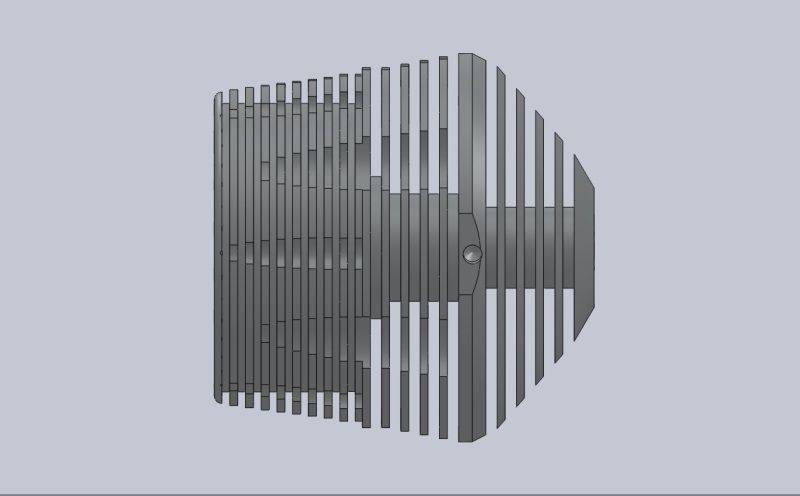
Here is the side view. Note the extra shallow groove a third of the way in from the left. It's not shown on my first render. The hole on the the thicker portion is for mounting. There is one the other side too as it will be mounted with a cradle held on by the bolts on my stem/face plate.
The scalloped portions seem to help with the turbulence, breaking up the boundary layer to draw the heat away. Without them, the air seemed to flow over the fins.
I know it would be much more efficient to have the fins running into the air flow but there is no way I'm going to be able to easily do that on my manual lathe! The model said it would stabilise at 34C though.
There is a hole at the back, either for a plug of a cable gland. I'll have the switch on a fly lead.
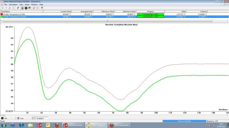
Here is the graph. I didn't run a transient (timed) test at my pc would have thrown its toys out of the cot, but you can still see the rise of the LEDs in red against the max temp of the housing in green. Once the templevelled out, the test stopped. Like I said earlier, I started at 60C to speed up the calculations. With a fine mesh setting and narrow channel refinement it could take upto 2 days to complete! I placed a local mesh at the front as I noticed that portion played the biggest part in getting rid of the heat. The rear section had a rough mesh to speed up things.
PilotPTK - I know I am late to this thread, but that is a very nice design. Great job with the thermal vias and the large copper areas for thermal transfer.
I really liked the small oval metal “posts” that solder to the board, yet by being hollow make it easy to attach a test probe - where can I find those? Who makes them?
Same here. I try/look for it first on Ebay :bigsmile:
Thanks Will - A lot of time and thought went into the design, and I’m pretty happy with it. The software/firmware is just as neat as the hardware though.
The test points are awesome. I use them for practically everything. Small enough to not be a real-estate burden, big enough to probe and super easy to attach test-leads to. They’re keystone part number 5015 http://www.keyelco.com/products/specs/spec130.asp
Mouser usually has them in stock, and I’m sure other places as well.
I order them by the thousand, because I really do put them on everything. One board I designed that’s full of analog and needs to be calibrated has over 800 of them on it. One Board. Ugly. Takes a good tech about 2 days to calibrate it. Couldn’t imagine doing it without good test-points.
Wow, thanks again man - much appretiated sharing the smaller footprint data. I use spring-loaded pogo pins for programming my Atmel Tiny processors, and for testing some small boards, but these SMT test points will come super handy as they free your hands and allow for a good/solid connection while testing/trying things out
For sure, the solid connections and free hands are awesome. Once you start using these things, it gets addicting - I put them on every signal line I think I might ever need/want to probe. They’re small enough that it doesn’t usually have any real effect on board size, and they are so nice to have when you need them.
The pogo pins are what I always use for programming headers
Unless I’m really tight for board space, then I use a tag-connect layout
Very cool. My programming setup is not fancy, but works well for the relatively low volume of my projects. Here I am programming a Tiny85:
And here is the programmed board on its battery carrier (cover off in picture, but bolted in place for end customer use). On this photo you can see the 7 test/program test points (some with silkscreen labels):
Sorry I haven’t quite been keeping up with this thread, but where are things at? Pilot, you have some already produced (fully assembled), are we just waiting to see what hosts will work well for it?
In terms of torches, yes - I still haven’t found a great host for it yet. A lot of people are inquiring about using these for non-torch applications though (bike-lights, off-road lights, you name it lights). I have some modules available right now for anyone who wants one - I haven’t announced major/general availability just yet because I’m still waiting for my shipment of U2 LEDs, and I don’t plan on running the big production run until I have everything (it costs big bucks to run on a U.S. production line for half a day).
Cool White T6 and Neutral T5 modules are available for purchase right now - I don’t have a lot of them though.
There was discussion in this thread about using this module with a D Maglite. After seeing this thread (3D Magmule with triple Nichia 219s), I think it’s very feasible to fit this module and a heatsink into the top end of the Maglite with a bit of boring (just above the switch) The stock head could then be milled down, or a head like the one cut on the lathe in that thread could be used to hold the module and optics in place. If the momentary configuration is desired (I would want that), the module could be hard-wired and the stock switch could be converted to momentary action for mode changing (or the stock switch could just be replaced entirely). Along with cutting down the battery tube and either using 3 x 14500’s or have it bored for 3 x 18650’s, this could be a pretty compact powerhouse.
PPtk: Quick question - can the momentary switch be wired to pull up (to positive) instead of pull down (to negative)? That way the stock switch converted to momentary could work as-is.
Unfortunately, no. The switch must be wired between the Momentary Contact Input and Ground. It is pulled up on the circuit board, and the switch pulls it low to toggle an input. Pulling the Momentary Contact Input to Battery+ would be very bad, in fact.