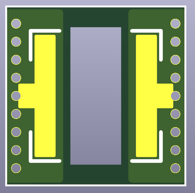
It’s a thin (0.15~0.2mm) flex board DTP adapter for soldering 3535 LEDs onto a 5050 board, sometimes using another MCPCB is not possible, or in the case of Zebralight for example there is no MCPCB to swap at all.
I didn’t compare performance, with the adapter the only difference is a 0.15~0.2mm solder layer between the copper base and the thermal pad of the LED, while solder has lower conductivity (50W/m.K) than copper (400W/m.K) it probably doens’t affect much heat transfer over such a thin layer.
I reflowed in one step, for the thermal pad I think it’s preferable to add solder to it before reflowing instead of paste though, since it need a certain amount to fill the gap, with a lot of paste it might make a mess.
Tinning the thermal pad should be easier, which I'll trial on one sample. But applying paste with a fine tip applicator with a stencil should offer more consistent results. I'll report back if I try these out.
So in all this is adding 1 extra layer of solder (0.15mm = 3.3e5 W/K each) and 2 extra layers of copper (35um = 1.1e7 W/K each) and the plastic film (0.1mm = 1600 W/K). Those combine together for a thermal resistance of 1590 W/K. Which is about 90x worse than the thermal resistance of a 1.5mm copper mcpcb with a layer of solder.
I would be very careful running this at high power!
Wow this is exactly what I’ve been looking for to use in my Zebralight sc600 mk2, I have a dedomed xm-l2 currently but looks like it’ll be getting a 519a!!
Interesting. I have a Nitecore HC60 headlamp with a 3v XM-L2 that I’d love to swap out with a 519A. This could be the trick. Thanks for coming up with this.