Still waiting on the 5V regulator chips but I’ve made up a dedicated board for the 4 7135 chips which is just a copper sink with a crenelated cylinder for the chips. I want to see how much excess voltage they can handle when they are mounted this way. They are rated to 700mW per chip in free air but the specs don’t give an absolute limit on wattage, just temp at 150C. As the chips are in parallel, each has to drop all of the excess voltage. One of the graphs in the spec sheets plots dropout voltage(voltage burned by the chip) vs output current and tops out at ~4V! At 350mA that’s 1.4 watts per chip folks! The heat sink capacity reccommended for them is WAY more than can be supplied by the boards we typically use and I suspect that even when stuck to a large heat sink the traces constitute a bottleneck in the flow of heat. Stay tuned.
Here are some pics:
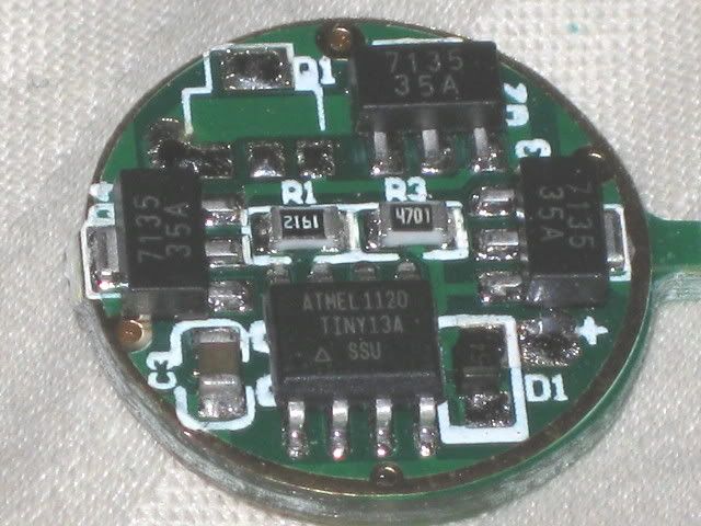
The first is a virginal Dx 7612 1A 16-mode board
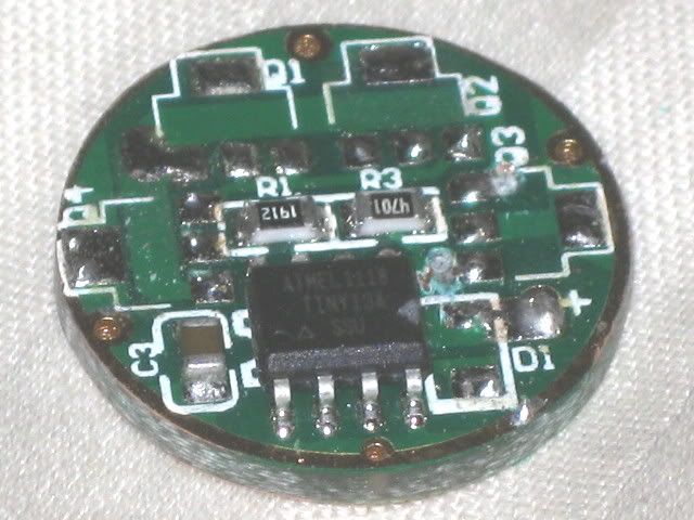
The second is another 7612 with the input diode and the three 7135 chips removed and the traces cut to the Vdd and output pins of the Q3 pads
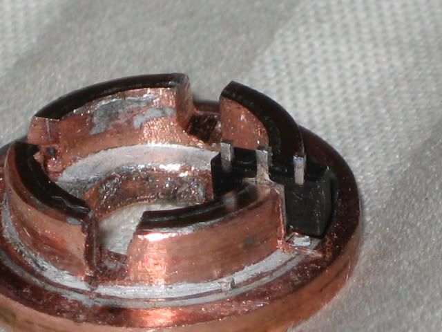
And the third shows the heat sink with one of the chips placed
I have several battery voltages that I can test and I want to find out how well this heat sink works. The sink will get some clean up work and pretinning done to it before assembly.
Running the LEDs in series is no more or less efficient than in parallel. Power loss = voltage drop across the 7135 chips x the current through each of them.
4 xpg in parallel from 4 Li-ion and 4 boards(1master, 3slaves) at 1.4-1.5A =
(4.2Vb - 3.3Vf) x 16(350mA) = 5.4W
4 xpg in series from 4 Li-ion and 1 board =
(4 x 4.2Vb) - (4 x 3.3Vf) x 4(350mA) = 5.4W
The difference between the two is the battery current (6A vs 1.5A) and the heat being dissipated across 16 chips vs 4. The input voltage to either the Attiny 13A(multi mode) or 7135 Vdd pin(single mode) is a separate issue with a separate solution. I believe it is the boards as currently used that limit the range of use more than the chips. While I don’t expect to be able drop almost 4V into each chip, I suspect we can do much better than 1V. If not, I’ll be sure to post the sauce I use on my crow dinner.
Sorry, I have not read the whole thread carefully but the way I understand this, in a PWM situation the voltage across the 7135’s can switch between 0V and 16.8V.
Have you considered that the 7135 are only specified to 7V max ?
Well, this could easily be remedied by a zeener diode across the 7135’s (z6.3V or like) to limit the voltage so I think that your circuit is sound enough.
Cpf Download shows in the thread kindly referenced by ChicagoX above how LEDs can be used to lower the voltage drop across the 7135 chips. The dropout voltage of the chips is the limiting factor here, not the total voltage of the system. I first read that thread before I even joined BLF and have reread it several times since then. Also, OldLumens thread, “the much sought after master/slave mod”, in which he collaborated with Cpf Techjunkie, has been a great resource. The ground work for this idea was laid in those two threads. The voltage drop in a system is equal to the sum of all of the voltage drops in that system. 7135 chips were designed as led drivers. It is assumed that at least some of the 6V max will be dropped across the “assumed” led. From the spec sheets, the actual max Vdrop is 4V and that only with very good heat sinking. As in Downloads version, I am using a series of LEDs to provide some of the voltage drop in the system. I am also using the Techjunkie method of splitting the Led circuit and the driver circuit and using a link wire to control the 7135’s as slaves. What I am adding is a separate method of lowering the voltage in the driver circuit.
When PWM switches the current off, the voltage drop across the LED’s will go towards zero at a speed determined by the capacitances in the system. Hence the voltage across the 7135 will rise towards the battery voltage.
But good luck with your project!
I had wondered about that(not really. I’m obviously not an engineer) but postulated, perhaps incorrectly, that the same situation occurs in Downloads method without negative effects and that maybe the location of the LEDs in the circuit was relavent only to the input voltage of the Attiny chip and the Vdd pin on the 7135’s. I’m just using a different method to lower ther processor input voltage than him.
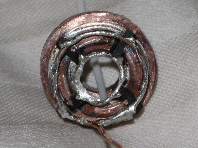
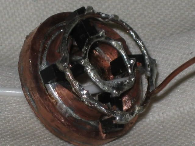
There is a picture of the sink in post #23 before I cleaned it up with one of the amc’s set in place. I pretinned the chips and the sink, cleaned up the sink a bit more, and then set the sink with chips on another layer of pretinned cu and reflowed the whole thing with a small butane pencil torch. When I saw the chips settle I removed the heat. The sot-89 plastic is undamaged so there’s hope yet for the ic’s Not at home for a few days but will check output when I am. Here are 2 pics with the chips wired. I used a dremel to grind off the ground pin in the middle for more room. To get a nice circle I pretinned the wire and then wrapped it around a screwdriver.
It’s a bit ugly and I’ll likely redo the outer Vdd wire but this should be fine for testing. Still needs a ground wire to the sink itself.
I wonder if what goes on in the Download version(extra LEDs in series with the driver to lower battery voltage) is that as the current goes to zero in the pwm cycle and the drop across the chip rises, since the current is going to zero, the power loss(and heat gain) is also going to zero. I don’t know, but his method DOES work so it must not be too much for the chips to handle. I expect someone with an o-scope could spot any voltage spike and recommend a possible solution if necessary. I don’t have one so I’ll be using the “if it ain’t broke, don’t fix it” solution.
I think that what saves the construction in #3 is that the spikes (at the + terminal of the driver) are dampened by the diode and decoupling capacitor associated with the MCU.
The voltage at the + side of the Attiny driver (and hence the Vdd pins of the amc’s) is limited to +5V by the L78L05 voltage regulator. Only the output side of the amc’s see these spikes. I don’t see how the input diode would affect them as that diode is not in the led current path but I’ll take your word for it if it does.
Anyway, the regulator chips arrived and I soldered one to the driver board at Q3 and jumpered the input and output pins to B+ and Attiny input . I still need to p/up an SMD cap to go from Attiny to the gnd ring and see about an axial lead schottky. The first test will be with a 7 nimh cell battery for the driver and 2 xre LEDs at 1.4A. I’ll have to verify the current output as well. This will tell me if the chip heat sink can handle ~2V+ extra and I’ll also measure the input voltage of the driver to verify 5V there. I can also check the temp. If all is good(still well below 120C) I’ll go up to 8 cells. It’s late so if I’ve missed anything I’ll check again before the tests when I’m back home again in a few more days.
The reflow of the amc chips to the sink worked fine. First reading was at 1.28A using cheap dmm probes, then jumped to 1.38A when I substituted some awg14 for the positive dmm probe(still with skinny negative probe). This was with the chips I removed from the 7612 board plus one other new 350mA bin chip from IS and a Keygos 26650 reading 3.85V no load. The sink temp was 35C. Moved up to 4 subc. nimh cells At 5.5V no load and was reading 52C. At this point I attempted to add in the processor board, go up to 7 nimh cells(8.8V) and two xre r2’s but the wiring was much too Cobb and I lost the solder ground on the sink and could not reattach it. I’m away from home again for a few days but will continue testing when I get back.
Not sure if this is relevant but xpg and XML both have a minimum Vf ~ 2.5V below which no current flows at all (right?). So when the pwm switches the current off, the voltage will rise toward Vbatt (at the 7135’s) but be cut off completely when the LEDs fall below Vf. So the maximum voltage the 7135’s would see would be 16.8Vb - 4 x 2.5Vf = 6.8V. If this is the case, that schottky wouldn’t do much would it? The voltage spike would already be clipped by the diodes.
I rewired the 7135’s and the sink ground wires and potted it. Also reworked the testbed to simplify/strengthen the hookups. I picked up a .1 and .01 microfarad capacitor and will add those to the processor board next time. Also a few resistors to play with. Took some pics then left the camera behind, oops.
Newest results- positive
I powered up the heat sinked 7135 chips and got 1.4A to an XML so that part worked but when I hooked the chips up to the processor board I got all the modes but low but at very low output(~50mA). I ran some continuity test and measured 0 ohms between Vdd and ground. I believe the problem is on the board so I rather quickly set up a new board but keeping the 7135 chips on board and adding the 78L05 as described above leaving out the extra capacitors and it worked perfectly!
I was able to drive 3 xre-R2 in series with one Dx7612 1A multi mode board from 9s nimh 4/5 sub-c cells(12V no load). I started with a 1 ohm 2 1/4 W resistor to lower the voltage a bit and measured (under load):
Vbatt 11.38V
Vf all 3 LEDs 10.35
Iout Hi 1.028A Med 335mA Lo 64mA
Vout 78L05 5.02V
With this set up the chips were not warm to the touch and the resistor was quite hot. The board was not heat sinked in any way.
I swapped the 1 ohm for a .5 ohm 2W resistor and remeasured:
Vbatt 11.35V
Vf 10.35V
The other readings were unchanged but this time the resistor did not get warm but the chips did.
Making the changes to the board took me about 45 minutes and included removing and relocating 1 amc 7135 chip, cutting 2 traces, adding 1 78L05 voltage regulator(looks just like a 7135), and adding 2 jumpers for the Vin and Vout of the 78L05 chip.
If you have added or removed chips from this type of board then this is a pretty easy mod. I use a magnifying lamp and sharpen my 20W iron.
Next I will try this on a 105C 3A board with some xml’s.
So far it’s been a diary of ignorance, education, failure, and more recently, success. I think the various parts have been proven. Now I need to finish it off.