Glad to hear it!
Welcome to BLF and I hope you continue to enjoy your visits here.
Glad to hear it!
Welcome to BLF and I hope you continue to enjoy your visits here.
Very interesting, thanks for the excellent details
1st welcome nazgool!
I wonder if youre capable of running 1h nonstop at 2,1A in the l2 host without overheating? I immagine you disabled 2 amc to get to 2,1A correct? Well if you did how much does mid an low draw now?
Where did you get this 105C version?
At KD.
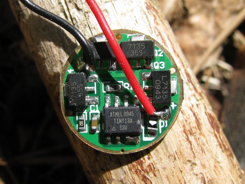
I cant show the led side as it sits in the pill, but the batteryside is here:
http://img502.imageshack.us/img502/2784/driverz.jpg
how do you remove the modules to lower amperage? is it just as simple as desoldering the right amount of modules? does it matter which ones? I want to drive an xpg with this driver..do I remove 4 modules to make 1.4a? can the xpg take 1.75a with 3 modules removed?
thanks
Instead of fiddling with small items try this or similar:
thanks Nautic..I already ordered the 2800mah one..wish I would have known about this driver before..so to mod the 2800mah one is it just deoldering the modules? if I mess it up ill just order that 1400 mah one..
edit: the ebay driver seems to be 1-mode correct? I needed multi-mode so this wouldn't have worked..
KD has this http://www.kaidomain.com/ProductDetails.aspx?ProductId=9606
Looks like a 3-mode. You have to solder the amc7135 here though.
so it doesn't matter what slots you take out or put in with these drivers? I have the 2800mah one on the way so I can just take off 4 chips and it will run 1400 mah?
That's right. They are all in parallel.
perfect thanks!
I am a newb to this, but I have decided to attempt the driver swap this evening. I have a couple questions:
1. Will the driver work fine with the small spring that was provided with the driver? or did you swap a bigger spring on?
2. Which of the holes is positive and which is negative?
3. Do you have any more pictures of this driver installed, or pictures during installation that I can use as reference?
Thanks again for any help!
Driver will work fine with the spring removed. The only question is weather the battery can make contact with the driver when the spring is removed.
What holes? the center circle connects to the battery + and the outer circle connects to the battery -
I don't take pictures when I install/solder a driver. can't multi-task (yet)
When I am soldering the pos. wire and neg. wire from the emitter to the new driver, there are 3 holes on the driver. Which of the three are the neg, and pos that I need to solder the wires too?
the three holes are holes to recieve the pos and neg. wires correct? as seen here:
Works fine with the little spring. I don't know that you could fit a bigger spring on there which is why they include the little one.
The holes aren't anything. If you look at the first picture in this thread, the positive is a little solder pad on the lower right, marked +. The negative is a little solder pad on the upper left. Those are for the leads that go to the LED.
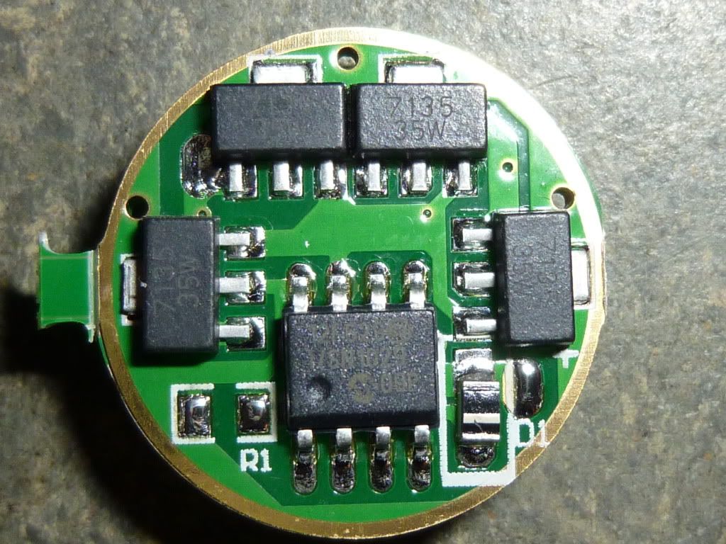
Here's a picture of a very similar driver with the leads installed:
http://budgetlightforum.cz.cc/node/289
Good luck on your driver swap! These boards are just ridiculously small and can be really hard to get soldered without burning other components or just missing the pad altogether. Try to test it once you get the leads on before you put the driver in the pill.
Bah, upon closer inspection I realized the holes where nothing lol. My bad. Thankyou for the help brted!!
I had to make the small spring a little longer to make it work in a P60 dropin.
I just bended a piece of cobberwire, stuck it in the spring and soldered it to it,
so it had the lengh needed.