interesting results, looking forward to the High results with the beefier resistors. Looks like the 7135s are getting the right voltage on medium but a rather low Vf - is that normal for that current draw (0.7A)?
I hear what you’re saying about the pull of curiosity! You’re clearly not doing this out of necessity
The goal at the outset was for 4 LEDs powered by 4 Li-ion and though I’m very pleased with how the 7805 is working I’m not overly confident about the 4x4. 2s2p I think is very plausible and 3x3 would be great. What to me makes this idea questionable is if you forget where a switch is set you could blow all the 7135’s by accident. Even if I can make it work, this represents a serious flaw. Oh well, one set of chips a week is less than popcorn money. To some I’m sure this seems a pointless exercise but it has been good practice and has taught me how to make a custom heat sink for the chips allowing installation in odd places. In any case it ran without incident on medium for another 20 minutes by which time Vbatt had dropped to 9.3V(recovered to 11.1V).
Also, the voltage measurements may be suspect since I am measuring a pwm signal which may not correspond to a current vs Vf curve. I use a lot of big words but I really don’t know s**t. Time for a beer.
I’m going to try this mod on 4 LEDs 2s2p with 8.4 V. Since the 78L05 requires ~2V overhead I ordered some LD2981 very low dropout regulators from Mouser which will stay in spec down to full discharge. Also ordered were some smt 0805 1 and 2.2 micro farad ceramic caps.
I think I may have discovered a relavant tidbit. When I tried this with the pack fully charged to 14.3V the chips died(gates lock open and can’t be dimmed). Remember, on low and medium I was measuring 7.3v - 7.6v across the emitters so the fresh pack was exceeding 4V across the chips even with the resistors. Even though the chips don’t even get warm on low and medium, they poof at to high an input V. I went over the 3 nimh/1 Li-ion per led limit. If this is the case, then 4 LEDs on low-med at ~10v and high at ~13.2v would stretch the ability of a resistor to both lower the voltage sufficiently for safe operation on low-med and maintain voltage s above Vf on high. At this point 2s2p might prove more reliable which is the reason for the Mouser order. For my next magic smoke, I’ll reload the sink with fresh chips and run the test again with 9 nimhs. For the record, I still haven’t spent enough on toasted chips to buy even half of 1 quality Taskled or Shark driver.
It may appear that you are talking to yourself, believe me when I say Ive followed this with interest even though I dont understand it. I may learn something if I'm lucky. Keep it up and good luck with the outcome.
Thanks, it does seem that way but I notice that some are reading( or at least looking at) this thread. Watching someone muddle through isn’t how textbooks are written but at least it’s genuine. Posting just the end result would be better as a “How Too” guide and I hope to get to that point but this is more of a journal.
I follow your so-called "muddling through" with scrutiny every day Rufusbduck
And I start to see some relevance to it too so keep it up. You are doing a hell of a job and I hope you will nail it in the end. Sure makes for some exciting reading :-)
I appreciate the vote of confidence. Heading home tomorrow to muddle some more. I have an XTE quad pcb with a 2s2p jumper option that I will set up on a cu cap to be ready when the new regulator chips come. This will use 2 sets of 4 chips each controlled by one Atmel chip(equivalent to 1-1.4A master and 1-1.4A slave). Testing for this will be later in the week.
I’m still following and it’s still interesting! Always cool to see an experiment in process, even if I only partially understand what’s going on and almost definitely wont benefit from the outcome
I just spent the last 1 1/2 hrs typing and my iPod just dumped it all $&@%#*€¥. I’ll repost tomorrow but suffice to say it works just fine in all modes with no added resistors.
Got home at night and loaded the heat sink with 8 new chips reflowed with Kester solder paste and reattached the mcu board, put 2 series 1/2 ohm 2W resistors in parallel with a 1 ohm 2W resistor to increase my wattage allowance. I used 14awg stranded power cord wire for my current measurements but the connections were made with just alligator clips. I recharged the batteries between each series of measurements all taken in the same order so although the voltage and current numbers don’t coincide, they do correlate.
Using 3 XML LEDs in series powered by a 12V(9s4p nimh 4/5 subc) battery pack 12.2V no load and 8 x 7135 on a custom heat sink slaved to an Atmel Tiny13A(DX 7612 w/o 7135’s) with a 78L05 voltage regulator I took the following measurements:
With .5 ohm resistance, Low .128A_v resistors 65mV_v emitters 7.36V_v driver 4.56V_v battery(loaded) 11.99V Med .763A_v resistors 391mV_v emitters 7.85V_v driver 3.28V_v battery 11.48 High 2.6A_v resistors 1.26V_v emitters 9.11V_v driver 100.03mV_v battery 10.12V(recovered to 11.3 )
With no resistors (drum roll please), went to sleep and charge battery overnight… Low .148A_v emitters 7.32V_v driver 4.82V_v battery 12.15V 21C at sink Med .875A_v emitters 7.86V_v driver 3.85V_v battery 11.61V 24C High 2.78A_v emitters 9.18V_v driver1.48V_v battery 10.55V(recovered to 11.84V) stable at 37C
When I put the thermocouple on one of the led sinks the temp did not stabilize before 70C at which point I terminated the test.
I think this calls for a BooYah! For any one that skipped the middle of this post I succeeded in running 3 XML’s in series with modes from a 12V supply to a maximum ~2.8A
Uses a voltage regulator chip (same size and package as 7135) to protect processor from higher voltage battery.
Uses the forward voltage of the LEDs to protect the 7135 chips from the higher voltage battery.
Good for modding lights that have series batteries( 3C,3D Maglights).
Good for lowering current from remote packs like bike lights or lower current switches
A battery pack with less sag will likely still need a resistor but I did everything in my power to push it. I don’t have any more cells to throw at it.
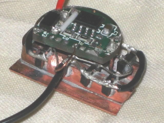
Current eta on the new LDO chip for the 8.4V 2s2p xte mod is Monday. I think I will use my 380mA chips for this one now that I know things work. There will be 8 chips in two sets of four(1.5A) with each set pushing two series Leds so each led will be safely driven at max. The heat sink is ready and the 7612 board is stripped with the traces cut and the excess board cut off. It will look similar to this but with two output wires(black one).
A next logical step might be to see if improved heat sinking would allow this mod with the 7135 chips remaining on the board. I have seen various attempts with potting but none that involve direct soldering to the board.
The new chips came today. These are very low dropout voltage regulator chips. They do the same thing as the 78L05 in lowering the input voltage to the Atmel Tiny13A to 5V but will operate down to a 2s battery voltage of 5.5V. The max input voltage is 16V so these are not an option for a 4s battery pack. The 78L05 has a dropout voltage of 2V and would only work down to 7V, good enough for >3s but not 2s. I should be able to play with one on Sunday. One disadvantage of the new chips is that they require input and output capacitors so the Mouser order also has some insanely small 0805 caps. More carrot juice please.
So I open up the box from Mouser and everything’s there, the new low dropout voltage regulator chips, the capacitors…(omg, ever try and solder a piece of coarse salt?). I actually knew how small they were because I sized them to sit end to end across the three pins of the regulator. Anyway, no need to worry about board space.
Skipping over all if the pita soldering the set up is similar to the previous one with these differences: Instead of three XML’s in series there are four XTE chips on a 25 mm quad pcb wired 2s2p. As before there are eight 7135 chips slaved to the modified mcu board but the outputs are split into two groups of 4 chips each. The battery pack is two Keygos 26650 4800mAH(right!) wired 2s. I kept the same set of resistors as before to allow me to ramp up the test to full Vbatt.
I first used a 1 ohm 4watt resistor(effective) and everything was fine. I measured the voltage drop across the resistor, each string of emitters, the driver, and the battery under load. I did this at low, medium, and high. I ran this series of tests twice more with a 1/2 ohm resistor and no resistor and as one might expect the emitter voltage increased in each series as the voltage across the resistor dropped. On the last test with no resistor and the driver on high the drop across the 7135’s measured 87mV(no load Vbatt was 7.95V by then) and the only thing getting hot was the LEDs. The highest drop across the driver(mcu+7135’s) was 3.25V on low with 1 ohm resistor. I’d have to conclude that this mod passed with flying colours. The next step will be to take one of my 3A Illumination Supply boards and run this test with the new regulator and the chips left on board. It’s almost 2am so pics of the setup will have to wait.
It works just fine leaving the 7135 chips on the board. Or , I should say, the second one works just fine. The first one died a fiery death under my iron so I hit the poor defenseless bugger with a hammer. Made ME feel better anyway. As I said, it works just fine using a voltage regulator chip for the mcu and up to 3 LEDs in series with an equal number of Li-ions(4 LEDs if 2s2p). I suppose various combinations like 3s2p or 2s4p using slaves shoul work as well. The main thing I’ve found is that virtually no heat is generated by the driver on low or medium and on high the heat generated by the LEDs far exceeds that generated by the 7135 chips.