They use thermal grease, not adhesive and they use all different types of clamping methods, to hold the heat sinks on. They don’t use adhesive because they can’t take if off easily and because clamping or hold downs are the only real way to hold two pieces together. We just don’t have that kind of room in a flashlight.
AA needs pressure and a lot of it to work properly as it’s not an adhesive - alumina adhesive would be what you’re after AA on newegg Plain AA works fine on CPU heatsinks as the clips/clamps/screws provide an enormous amount of pressure, but wouldn’t be any good for a component left floating around ![]()
I’ve always screwed my LEDs down on all of my builds, although I tend to have more room to play with. You can get sweet little allen cap screws with 4#40 threads that fit within the holes on the star, those might help. I have a draw full of them (scavenged off an old microscope filter wheel) if you want any - I’d have to build 20 or 30 lights to use all of them, which, you know might happen {tick, twitch}
I have 3mm screws. I just hate to do it. It's such a PITA. I will be using screws on the SST-90 instead of AA.
AA is good to 150c, but unfortunately, that is lower than the 185c-190c of 60/40 solder. No wonder it never works. So, that means solder before, glue after. Another PITA.
I think maybe it's just the 100+ degrees every day that's a PITA and it makes everything else seem to be. 
I dunno, it only adds 10-15min to my builds. Mark, punch, drill, tap, blast with compressed air and you’re done. 100% reproducible top notch thermal junction everytime plus replacing the LEDs with the next model out is a piece of cake.
Epoxy sort of has a “memory” for the highest temp that it has seen. Heat it above that and it softens. There is (somewhere) an article on boat repair on the Gouegon.com web site that talks about it. Gouegon makes the West Marine epoxies.
Real high temp epoxies have to be baked to set the epoxy and get the high temp capability.
Blown away again. How do you get your soldering so neat? Lots of practice and ability I suppose. If I did what you have done with those drivers there is a 100% chance that they would never work again. The close up picture's aren't bad either.
Truthfully, I get nervous every time I have to go near something like that. I hate soldering those things! I have a table top light that has a big magnifying lens in it. I can pull it over top of the work area. I also have to position the boards in a small vise, where they cannot move and where I can rest both hands on it. Otherwise I can’t hold still enough. It’s hit or miss and y’all don’t get to see the mistakes, LOL, but mistakes, they are a plenty, believe me.
I would love to buy a real micro soldering gun or station, but the good ones, with the really thin tips, are way too much money. I usually file my tips to a finer point, even though it ends up ruining the tip much quicker, but I can't solder that stuff with a regular tip. I know one thing, you want a good, hot iron. At least 40 watt or more. It is so much easier to just hit the spot for a second, rather than to have to hold in place, waiting for things to get hot. I never knew that, till I read it from another member. It works!
If I may ask what mixture of lead/silver, flux or resin cored and thickness solder do you use. The array is amazing.
I use 0.032" solder, 60/40 rosin core. I get it from Radio Shack in spools and wrap a few yards at a time on a 3/8 rod, so I only have to hold the small coil when I’m soldering.
That looks to me like some very fine soldering work. Mine is improving but not yet ready for prime time.
Hi Oldlumens,
I have to say I am very impressed. Even at a glance the level of quality you are able to produce without the benefit of expensive equipment is clear. The amount of patience shown in your work is admirable.
I think the upgrade to the battery carrier is probly the most creative part, it has a professional look about it too.
This is not a criticism, merely an observation based on my experience. The addition of those extra chips being soldered on top of each other is probly going give you the opposite effect of what you are looking for.
Heat is a very serious issue with these 7135 circuits ( as you probly know). Piggy backing those chips like that will compound the issue. I have found without exception when these boards are slaved it also causes a heat issue.
My personal SST-90 mglite is powered by a set of 3 drivers like that ( not as pretty as yours  ), but in order to keep the current stable I had to heat sink both sides of the boards to fairly thick aluminum plates that touched the outer light wall. Without this the current will fall like a rock around the 1 minute mark till it bottoms out at like only a couple of amps.
Thanks for sharing man.
My admittedly limited experience has been that the thermal issues can sometimes be attributed to excess heat from the LEDs. If the led sink is capable of maintaining a constant temperature then you could be okay. If the sink gets hot then the chips will get hot even if they are not being overdriven.
very impressive build so far… i love the sst90 led… i have a 3d mag with der wichtel 9a buck driver… cool stuff ![]()
Heat sinks arrived today. I bought these from Speedy Metals.
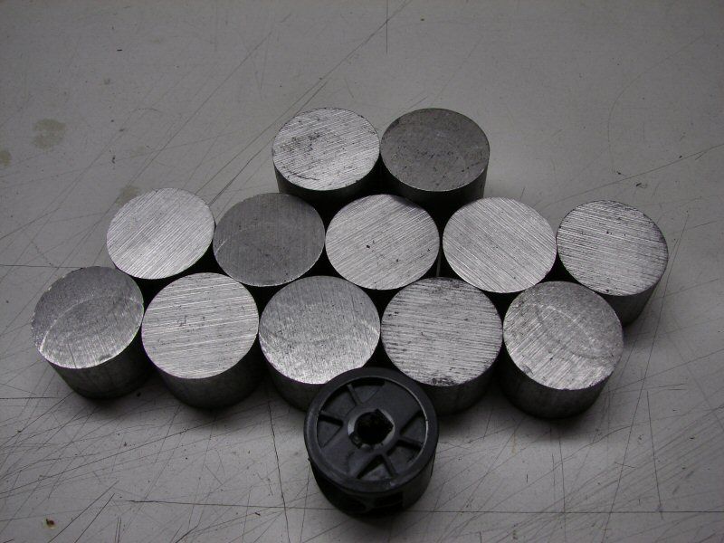
They measure 1.316-1.317" OD and a typical Maglite ID is from 1.340-1.344", so I will need anywhere from .010-.012" shim/sleeve, to make it tight in the tube.
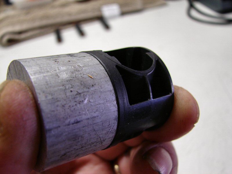
They are 1-5/16" aluminum rod stock. It's as close as I am going to get for a Maglite heat sink, unless I have some machined. I will tell you why I do not have some machined. These are about $2.00 each, shipping included. I can live with having to sleeve them with 0.010" copper or aluminum sheet, to make them work. It's close enough for me and it works for the budget. That's what it's all about here isn't it? Trying to make something that works, with what you can afford. Even if it is just a shelf queen.
This week-end, hopefully, I will get to work on finishing this build up.
I would say that I’m surprised the couple of extra chips would do so much to overheat. I haven’t experienced that yet, but there’s always a first time. The drivers will have a heatsink, but I wasn’t planning on a heatsink sandwich. I guess I will find out fairly quickly. Thanks for the heads up.
I also plan to include 3 dummy AA NiMHs, just in case I need to do the pack as 3S/3P, instead of 4S/3P.
Updated the first post. It works! Sort of.........
very nice project,nice mod you did with the drivers.
Very interesting idea regarding the LED on copper: reminds me of a Led Lenser H7 knockoff I pulled apart a couple of days ago, the leads were wired on the bottom (XR-E) and the center of the LED was pressed (no solder) onto a central plateau.
If you could find a way to electrically isolate 3 pieces of copper while still allowing them to shed heat-easily you could potentially have a quick and easy way of making direct copper bonded LEDs… something like this would work well for isolation and heat transfer: http://www.e6cvd.com/cvd/page.jsp?pageid=309&prod=16 might get a pit expensive though ![]()
Are there any real benefits to in increasing heat conductivity to the cathode and anode of the LED?
I wished I had your skill.
Very impressive.
Its looking really promising. You will be in trouble when the people who were talking about the bright light find out who it is. Looking forward to your night shots.