how do you remove the modules to lower amperage? is it just as simple as desoldering the right amount of modules? does it matter which ones? I want to drive an xpg with this driver..do I remove 4 modules to make 1.4a? can the xpg take 1.75a with 3 modules removed?
thanks Nautic..I already ordered the 2800mah one..wish I would have known about this driver before..so to mod the 2800mah one is it just deoldering the modules? if I mess it up ill just order that 1400 mah one..
edit: the ebay driver seems to be 1-mode correct? I needed multi-mode so this wouldn't have worked..
so it doesn't matter what slots you take out or put in with these drivers? I have the 2800mah one on the way so I can just take off 4 chips and it will run 1400 mah?
When I am soldering the pos. wire and neg. wire from the emitter to the new driver, there are 3 holes on the driver. Which of the three are the neg, and pos that I need to solder the wires too?
the three holes are holes to recieve the pos and neg. wires correct? as seen here:
Works fine with the little spring. I don't know that you could fit a bigger spring on there which is why they include the little one.
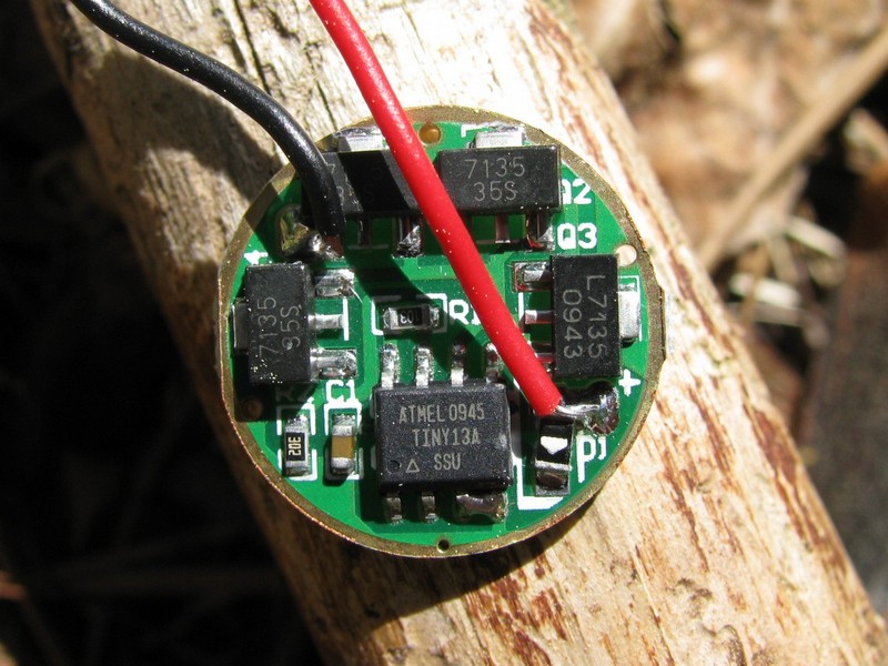
The holes aren't anything. If you look at the first picture in this thread, the positive is a little solder pad on the lower right, marked +. The negative is a little solder pad on the upper left. Those are for the leads that go to the LED.
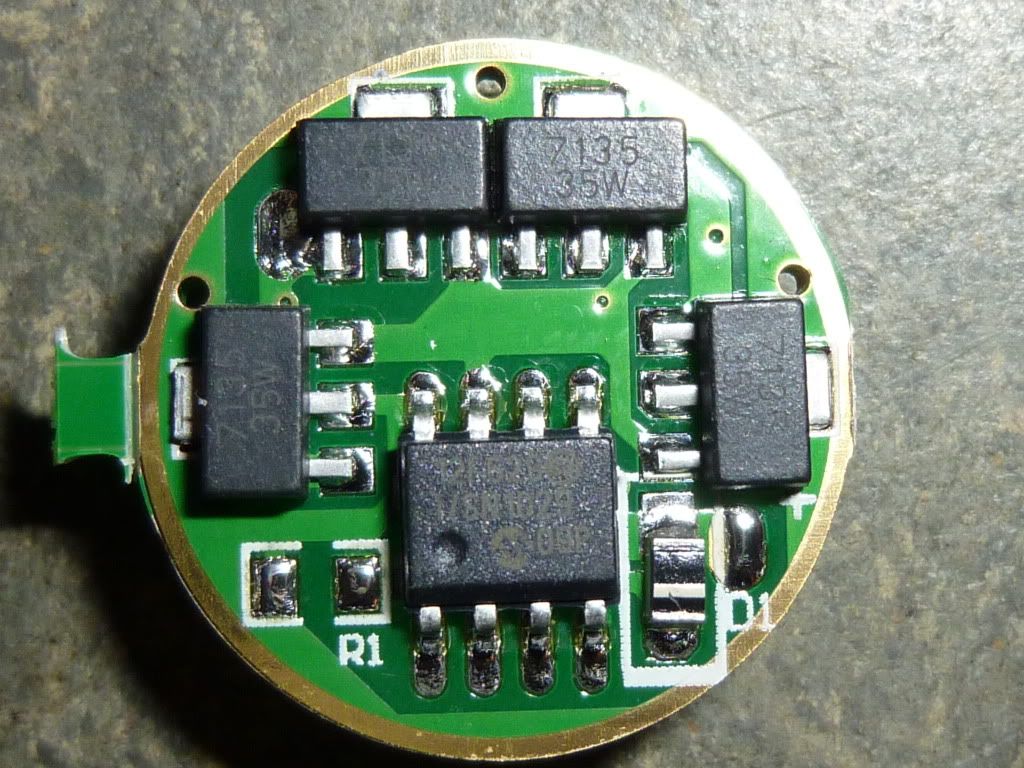
Here's a picture of a very similar driver with the leads installed:
Good luck on your driver swap! These boards are just ridiculously small and can be really hard to get soldered without burning other components or just missing the pad altogether. Try to test it once you get the leads on before you put the driver in the pill.
When i don't use a spring i put a solder blob on the pad. Be sure to not mess with it and do it quick. Works fine with flat head bateries. It's not a very good approach but i did not had any troubles so far from the solder oxidation yet, You can also use a tiny copper or brass (less oxidation issues) spacer if you so desire but make sure the tailcap have a spring. When doing high currents might be a good idea to avoid the excessively tiny/skinny springs. The normal ones are just fine, trim them if space is lacking. Be sure to not have the trimmed spring scratch the battery, bend the edge to the inside a bit.
Do it reasonably quick and don't overdue the heating. Pointy soldering iron tips are preferred. Good solder with some lead and flux is the best and melt pretty quickly.
just soldered an xml with this driver..first ever..it was really easy..I was impressed with my rookie skills..the leads were not connected on my driver, so I had to solder them on myself..I used a piece of 14 gauge copper wire to make the positive connection to the battery from the srping..it didn't work with just the spring..it was a great time soldering..I really enjoyed it..
as far as the driver function goes I really hate the 2 secs on for mode memory..I have never had a driver like this and it's really backwards to me..hopefully I get used to it..
I don't like it either, but I think all of the NANJG drivers are the same way (I've gotten used to leaving the light on for a couple of seconds whenever I use it). The micro-controller can't remember the mode after you cut power to it, so it remembers it after it has been on for 2 seconds. I like lights that remember the last mode after they are Off for maybe 0.5 to 1 second, but I think you have to have a capacitor or something that will maintain power to the controller after power is cut in order to do that.