Tido, that Bus Pirate looks pretty cool. Looks like I'd have to break out an Ubuntu live CD(or other distro) to use it. I used to dual boot with Ubuntu, but I eventually gave up that partition, as I found that I didn't use it very much.
Have been thinking a long time of how to make the best mode arragement (for me). The last one I made was 4 lm - 16 lm - 64 lm - 250 lm with memory (XP-G in WF-502B) where modes repeated in ring: verylow -> low -> mid -> high -> verylow etc.
The memory was handy but the number of tabs to reach a certain mode from turn-on of course depended on the memorized mode. The goal is to reach the most used modes with the fewest tabs.
A light with no memory would fullfill that and always have the same number of tabs to reach a certain mode and disco modes could even be added at the end:
low -> mid -> high -> verylow -> strobe -> SOS -> Beacon -> low etc.
For a XM-L light this could be:
32 lm -> 125 lm -> 500 lm -> 4 lm -> strobe -> SOS -> Beacon -> low etc.
I think that 32 lm would be a fine standard level for close use and the light would always start in that level. But for other uses it would be better to start in another level. That gave me the idea to combine the no-memory list with a memory giving this mode array:
last_mode -> low -> mid -> high -> verylow -> strobe -> SOS -> Beacon -> last_mode etc.
When the light is turned on it will start in the memorized mode. One tap wil bring it to low, two taps to mid and so forth. If the last_mode was low, one tap of couse should go to mid but that is easy done in programming.
The memory could kick in after staying a few secs in a mode or 1 sec after switch-off.
If memory is made after switch-off it opens up for an alternative arrangement with normal modes in one chain and disco modes in another:
Turn-on, wait 1 sec -starts in normal modes chain:
last_mode -> low -> mid -> high -> verylow -> last_mode etc.
Turn-on + fast tab -goes to Disco modes chain.
strobe -> SOS -> Beacon -> strobe etc.
Now I "only" have to modify Tido's program to test all this.
EDIT: For implementation: Look at post #254
Just to update you guys, I took your advice and ordered the 3M clip from here...
http://search.digikey.com/scripts/DkSearch/dksus.dll?KeyWords=923655-08-ND
They are only a state away, so it arrived really fast and shipping was cheap. The clip really locks on to the chip tight, but the contacts just barely didn't reach. So I had to trim the plastic down a bit, and then it wouldn't stay on :( After trimming it down multiple times, I think I have it working. However, I don't have a working chip anymore to test my latest program. Hopefully the shipment from Kaidomain will arrive shortly and they will have the Atmel chips.
...just really busy.
I started at a new job last week and I'm still looking for a flat. So it might take a few weeks before I find time to hack the driver code again.
We apologise for the inconvenience.
I'm glad you can find some time to be around here - thanks for all you've contributed here.
And good luck with finding a place to live, that is just about my least favourite task.
Hop it doesn't take too long.
ordered: 16 Feb 2011
Recieved 04. March.
5x 10⁵C ATtiny13A
This is a follow up on post #249.
I finally managed to squeeze the code for my dream light in. The space for code is 1024 bytes and I needed 1070. It finally came down to 1018 bytes mainly by rewriting the delay code and avoid using sleep_ms() and sleep_sec().
What about a light that tells the battery voltage?
It could certainly save a lot of unscrewing the tail cap to check the battery. Well, it is here now.
My wish list was:
1. Most used levels first. No need for programmable.
2. Many modes including flashing modes at the end of menu.
3. Memory, but no tapping through disco modes to get back to the first levels.
4. Battery read-out.
5. Shall decrease output gracefully at about 3.0V (for non protected cells)
6. Beacon mode should be the soft on, soft off type (byte-hungry).
The solutions:
1. Start with 'low' which is 44lm for this XM-L based light. Then higher plus a low-low.
2. Se mode list in point 3.
3. It memorizes a mode when used 2 secs.
[EDIT apr.15-2012] Memory can now be switched off, look here.
At turn-on after being off for more than 1 sec it starts in the memorized mode which alway has the first place in the menu which can be tapped through:
Last_mode ->
44lm -> 168lm -> 690lm -> 6lm -> strobe -> police strobe -> Beacon -> SOS -> (folds back to 44lm, NOT Last_mode)
By tapping from Last_mode it always go to 44lm*)
*) skips to 168lm if Last_mode was 44lm
4. Battery read-out is build into the Beacon mode. One second after the full power beacon-flash the light makes a number of countable blinks, separated 0,5 second. The level is 1 (1/255 of full power), the lowest possible.
examples: Vb= 4.2V -blinks 12 times
Vb= 3.8V -blinks 8 times
Vb= 3.2V -blinks 2 times
Vb= 3.0V -blinks 0 times
It is very stupid to look into the light to count pulses, the beacon flash each 8 secs is formidable, but using the reflection from close distance from a wall gives an easy count.
5. Output is cut in half in all modes each time battery voltage sinks to 3.0V until only the driver uses (a very little) current. This process can take 2-3 hours and optimizes output.
I have build this into a Solarforce L2 copy with XM-L and driver 105C plus into two WF-502B with XP-G R5 and driver 101-AK.
I'm a little euphoric about that L2 and it shows how far Tido's initiative from nov.2010 can take you.
Very nice. And all in 1018 bytes!
Hi all, first post here. I was just directed to this post and found it quite an interesting read.
I did the same thing nearly a year back now (doesn't feel that long ago) rewriting the uCs on the 7135 drivers. I am in the position of using various Cree LED emitters of different max current ratings (XRs, XPs, XC-E and hopefully I’ll get my hands on an XM-L soon) always with single Li-Ion voltages (though usually a few cells I've welded in parallel and wrapped, for increased run-time). This meant it was just as efficient to use these linear drivers as making a buck driver, though not as flexible.
I must admit that I found programming PICs in general to be much easier and user friendly than the Atmels. I ended up getting the basic software PWM down to around 22 bytes and the entire program down to around 210 bytes. My uC was independently controlling 2 different LEDs by monitoring 2 input switches, allowing the user to program up to 10 modes per LED. Of course changing this to just one LED and one input would be easy enough.
Of course this was all in assembly which I'm surprised to see has not been used by anyone on this thread. Given how basic the chips are, and how simple the program is it would seem an ideal place to use it.
Personally I do hope the drivers start using PICs again :p But I have seen that the couple of people who are doing the programming in this thread didn't get on with them so I guess its swings and roundabouts.
Actually, I have successfully ported the driver to the PIC12f629, I just didn't have the time to clean up the code enough for a release. I hope I'll come around to it once I'm settled down again.
Aloha and welcome to BLF Subterranean!
I have read through most of this thread, but it is packed with somewhat confusing information...can someone give a quick recap of it?
What components do I need to order to reprogram my own drivers?
PS: I have never done any programming with code but I am pretty computer savvy and hopefully can figure it out 
Hey cessna,
That's a good idea to summarize this thread. It's always a pain digging through all posts. So here's my summary of what I have been able to do.
Programmer: USBTinyISP - it's a parts kit, but the assembly is quite easy as long as you have a soldering iron with a small tip and thin solder.
Clip to connect on the microcontroller: http://search.digikey.com/scripts/DkSearch/dksus.dll?KeyWords=923655-08-ND - however, you will NEED a ribbon cable to hook this up to the programmer. I used one from the cheaper clip (blue one) I had which broke, otherwise you can find combo deals on ebay by looking up "SOIC clip", just make sure it's an 8 pin.
AVR Studio if you want to write your own code: http://www.atmel.com/microsite/avr_studio_5/default.asp
AVRDUDE program Tutorial for flashing the chip: http://www.ladyada.net/learn/avr/
From there I was able to buy some 7135 based chips with the Attiny13A chips from Deal Extreme or Kaidomain, download Tido's code (which includes a great README and pre-configured builds all set to flash), simplify his code to remove voltage monitoring and implement my own UI (and to understand what it's doing), connect the programmer up to the chip using the 3M SOIC clip, flash it, then solder it up and test it out.
Hopefully that helps?
- Jon
Maybe we could write a Wiki for how to do this? I have set up a page and done a rough draft. Since I've never actually gotten this to work (I think I need to buy a new clip, but maybe a new programmer as well) I won't be able to offer a lot of expertise.
Anybody can sign up at Flashlight Wiki for an account and then PM me to activate it so you can actually edit things:
sixty545,
can you share your code?
kong.
Of course I can share the code. I have DropBox, but have not tried to share files before, so I have to try first.
I use both kinds of memory that Tido's program support, memory after 2 sec on to remember the last used mode, but to distinguish tapping from longer_time_off I use memory_after_off which Tido calls "pin switching" because the function depends upon a capacitor connected to a pin of the MCU. At short "taps" the pin voltage is high, at longer "off" the voltage has bleeded away through a resistor. This function is discussed from post #166 onwards and calls for mounting 3 small components on the driver like this:
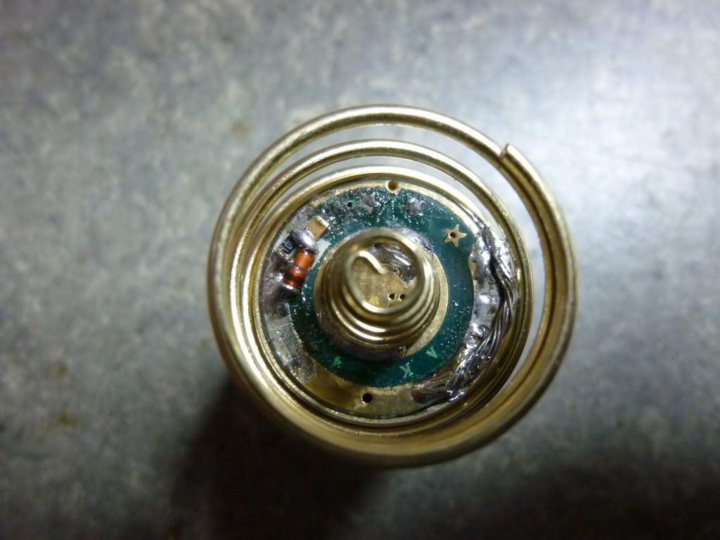
The 3 tap-detector components mounted on an AK47. Notice also how I connect the driver to the pill with a piece of multi-strand wire. I can then easily access the component side for re-programming by lifting the driver opposite the wire which is twistable.
I think it should take only a small modification to the program to avoid the additional components and use the 2 sec timing also for tap-detection. Of course the benefit of pin-switching will then be lost. I will try making such a version before sharing so it will take a while. But I will report back here when ready for sharing.
[EDIT]
Unfortunately it seems to be quite difficult to avoid having to add the 3 SMD components to the driver as the program code grows to be 48 bytes too big by omitting pin-switching. It think part of the programme has to be written in assembler to fit the available space of 1024 bytes.
For those still interested in my 8 mode driver with special memory and battery read-out I have made a zip-file here.
sixty545,
Thanks for sharing your code. I have an on STK500 dev kit with some spare Atmel 12 and Atmel 13. I can try to convert the code to assembly. I will need some help with the electronic..
kong.
is this clip sufficient? (12 dollars shipped) It looks like it has a nice small head for tight spaces, and it comes with a cable with a 10 pin female plug.
does this programmer look ok? (10 dollars shipped) It has a male 10 pin on the board, and the clip above has a 10 pin female. That should be a direct plug in right?
So with those 2 components in hand it comes down to software and the knowledge to do the programming? This is exciting!
ps great job on getting the wiki started brted!
Both those will work, they are both the cheapest (and most likely to break quickest) versions, but if you're going to flash a handful of drivers you probably don't need anything more expensive
.
However, it probably won't be a direct connection; you will need to change which pin on the clip each wire from the programmer connects to. To do this, find the pinout of the programmer (all similar AVR programmers will have the same pinout) and match it to the pinout of the attiny13 (and hence the clip). Depending on how the wires are connected to the clip you might need to desolder/solder but someone who’s done this already can better advise.